| Followers of this
series of articles may have noticed my failure to address
propeller efficiency in any detail. The fact is, that there
is a great paucity of measured information on propeller efficiency.
This applies to full-size as well as model propellers. I have
never seen any data on efficiency from the model airplane
propeller manufacturers. My article on the Travelling
Dynamometer is a portent of what is to come on this site:
that device at least permits the measurement of propeller
efficiency over a limited range of airspeeds and RPM.
Part of the problem with measurements of propeller efficiency
is that there is no single such thing. The performance of
the propeller depends on the inflow field, which is set by
the shape of the installation; it depends on the operating
conditions of airspeed and RPM; and it depends on the firing
cycle of the engine/motor. Any single set of conditions is
generally not enough information.
For this reason, there is a strong temptation to calculate
the efficiency from simple vortex theory. My experience is
that this is a risky approach; one can easily be in error
by a factor of 2! So where does one go from here? Well, there
are 2 components to efficiency, the profile efficiency and
the induced efficiency. Consider first "induced efficiency".
The induced efficiency is related to the speed of the slipstream
generated by the propeller. If you get your thrust from a
small diameter propeller with a high velocity slipstream,
you probably have low induced efficiency. In a companion article,
I will show how to get a handle on induced efficiency based
on the known parameters of the propeller, and its speed through
the air. For the present article, I will consider profile
efficiency.
Profile efficiency is related to how well the propeller airfoils
perform. If the airfoils are well reproduced, and the blade
has high angles as measured against the plane of rotation,
then profile efficiency can be high. Because propellers are
twisted, the profile efficiency is going to vary along the
blade. Furthermore, because the speed of the air passing over
the propeller blade varies radially out to the tip, there
will be other factors to consider, such as compressibility,
shock wave formation and Reynolds number. All 3 of these factors
will affect the lift-to-drag ratio of the airfoils, and hence
the profile efficiency.
One reason for not computing the profile efficiency is that
the lift-to-drag ratios at Mach number approaching unity are
not known. For low rotation speeds, this may not be a problem;
in that case, one may use the chart in my book "Propeller
Dynamics" for determining the profile efficiency. However,
in high performance model work, such as F2A control-line speed,
and F3D pylon race, tip speeds are close to Mach 1 and we
are in a world of pain. There is an interesting formula relating
to high speeds, known as the Glauert-Prandtl rule. I would
rather pull out my own teeth than use this formula, but I'll
give you a look at it here.
"The Glauert-Prandtl relates the lift coefficient or
slope of the lift curve of a wing section in compressible
flow with that for incompressible flow". Note that I
have swiped this line from p256 and Abbott and Von Doenhoff.This
way you cannot blame me when the going gets tough!
With Cli the lift coefficient at low speed (like 10 MPH),
and Clc the lift coefficient in compressible flow (say 600
MPH), then:
Clc = Cli /(sqr(1-M^2))
where M is the Mach number (airspeed divided by the speed
of sound), and "sqr" means "take the square
root".
If one chooses to calculate values for 1/(sqr(1-M^2)), one
sees that they start at unity, then, slowly at first, increase.
But above about M = .5, the values start to increase rapidly
and approach infinity at Mach 1 (M = 1). Now that is bit of
a worry!! Maybe this is where the idea of the "sound
barrier" gathered some force!
In a word, as the airfoil moves at high speed, its characteristics
change. It behaves as though its thickness and camber were
increasing. This must be allowed for when calculating the
profile efficiency near the propeller tips, in most applications
involving engine driven propellers.
However, before one gets much past M = .7, other nasty things
start to happen. Yes, shock waves start to grow on the airfoil
upper surface, and all your nice calculations with the Glauert-Prandtl
rule get tossed out the window.
Refer to my article "Transonic
Airfoils for Propellers", for a description of shock
waves.
For a long time, I have been living with this problem of shock
wave formation on propeller tips, especially F2A and F3D.
These classes typically run tip speeds of M = .95; they are
one of the most intense continuous sources of noise on the
planet. The way to control shock waves, in conventional practice,
is to make the propellers very thin and run them at low lift
coefficients. But at M = .95, you've basically had it. When
I say very thin, I mean we are down around .010" thick
at the tip, and not even carbon fibre can provide a stiff
structure then.
So what to do? We can't get the profile efficiency because
we don't know what the airfoils are doing near the tip. But
help is at hand!!.
Here come the cavalry! Roughly 70 years late, but still blowing
their bugles!
Back in good old Fascist Italy, circa 1931, the Alessandro
Volta Foundation ran a series of conferences at the Royal
Academy of Science in Rome. In alternate years, the Sciences
and Humanities were given equal billing. From September 30th
to October 6th, 1935, Mussolini extended his patronage to
the 5th Volta conference, on the subject of High Velocities
in Aviation.
It was there that the German scientist Adolf Buseman first
propounded a theory which applied the sweep-back of wings
to improved aerodynamic performance at high speeds. And that
evening, Buseman sat down with head of aviation research in
Italy, General Arturo Crocco, to review and interpret Buseman's
theory. General Crocco sketched on a napkin a propeller with
swept back tips, and suggested that this was the design suggested
by Buseman's theory. Indeed it was, and a great insight into
a problem first encountered by propellers: the formation of
shock waves near the tips in aircraft such as the Schneider
Cup seaplane racers.
Buseman went on to work in aviation research, in Germany,
during the war. He subsequently was taken to the USA to work
there. In 1944, R.T. Jones at NACA independently came to the
concept of swept-back wings. A 1943 paper by Quick described
German research into the use of sweep-back on propellers,
and claimed some advantages. The term "some advantage"
has a piquant meaning here: most propeller designers would
kill their grandmother if it meant they could get an extra
1% gain in efficiency!
Subsequently, the Curtis-Wright Corporation flight tested
a swept propeller, and NACA tested swept propellers in their
16' tunnel. Whitcomb designed a propeller with 45 degree sweep-back
at the tips, and these were tested. The results showed only
a small improvement, compared with that expected from simple
sweep theory. To quote from a NACA source:
" an unswept blade of slightly reduced thickness could
always be found which would have equally good high-speed performance,
better overall performance, significantly lower blade stresses,
and freedom from the other structural complications of the
swept propeller. This emphatic and disillusioning result put
an end to any further attempts to exploit swept propellers"
So there! Well this was disappointing, so I did a Google search
for "swept back propellers" and this is what I got:
"Considerable sweep back is helpful in allowing a propeller
to more easily shed weeds". Huh!?? Blow them INTO the
weeds is what I had in mind!
Now everyone who knows Supercool, also knows that Supercool
is always right, and everyone else is also wrong: even if
that means the great Whitcomb! Also, nothing NACA has done
invalidates anything I do!! Well I'm not afraid of blade stresses,
I can't make my sections any thinner, and I've got my back
in a corner! Also, I want to be a Legend in my own mind, so
it was off to the theory book to see what I had to do to get
a swept back propeller.
So what am I trying to do? Well I'm trying to fool the propeller
tips into thinking they are going slow and thereby not forming
any shock
waves! This way I can use my existing low speed data, as there
is no "shock stall", or "force break",
or whatever you want to call the shock wave problem. It turns
out that this is just what "sweep back" does do.
There are various ways of looking at this, but here is one,
not unlike the one given by Hoerner.
When the air approaches a swept-back wing, it can be considered
to have 2 components. One component points down along the
wing, while the other points across the wing, at right angles
to the leading edge. Both of these components have lower speeds
than the incident air. The component down the wing does nothing,
as it is not following the shape of the airfoil. The other,
going across the wing, sees the airfoil, and produces lift
according to its lower velocity. This means the Mach number
is effectively reduced by cosine(b) where b is the angle of
sweep.
If this is true, then one can choose the highest Mach number
one wishes, say 0.8, and increase "b", the angle
of sweep, until the cross component of flow has M < 0.8!!
What a piece of cake, this is a Supercool must do!!
Well, it took longer than I expected, because the prop sweep
has to curve back on a circular path, while with a wing you
just bend the whole lot back. More code, more bugs, but the
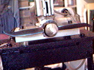
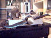
end result is rather cool
 |
|
 |
|
|
| Click
to enlarge |
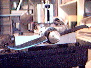
Testing has begun, and so far the props have
not shed any blades or twisted themselves into knots. Neither
have they gone fast, but 280kph at 29000 RPM is as good a
start as any. Watch this space!!
One final thing. Recall we set out to get profile efficiency?
Well with the shock waves gone, we can use the graph in "Propeller
Dynamics" to make a good guess of the profile efficiency.
For F3D, the blade angle is something like 27 degrees at 80%
radius, which is a representative point to choose. To be pessimistic
(which is to be wise also!) lets take the airfoil L/D to be
20. Then the profile efficiency, read from the figure, is
about 0.87. That will have to do. So the highest efficiency
the prop can have (since we are ignoring the induced efficiency
component) is 87 percent. Things can only get worse from here,
so watch for my next article!
--------------
The theory of sweep-back in wings is given
in the following link. My thanks to Thomas Eroksson for this
information.
http://www.desktopaero.com/appliedaero/potential3d/sweeptheory.html |