Ever had that floating
feeling? You know the one: you’ve just entered the outside
loop of a vertical 8 and the line tension has vanished: or
you’re battling the wind and turbulence in the overhead
8, and the model is in free-flight!
Wouldn’t it be great if a giant hand reached out of
the clouds to pull the model tight on the lines again? You
betcha it would! What you need is an automatic line-tension
compensator, right there on the model! Here is how to get
one!
The usual ways of controlling line tension are engine offset,
extra speed, line rake and fin offset. These all affect yaw.
During manoeuvres you may try differential flaps, extra tip
weight, moveable rudder, etc.
But the truth is this: none of these really work. Roll out
and yaw give you rock and roll in the squares, not at all
nice. Speed is good, say 4.6 seconds per lap. But who wants
to fly that fast, like in diving for the outside square entry!
This is an intractable problem.
The best solution I have seen to date is in the old Thunderbird.
This model worked well with lots of rudder offset and forward
lead-outs: even so, this model like to fly fast, not so good
slow. This is how it worked. The rudder tried to yaw the model
out, while the lead-outs tried to yaw it in. Slack lines meant
that the rudder won out, so that the model could yaw out,
restoring line tension. Well and good, but not as positive
as I would like.
Recently, the problem has arisen in my “Heart of Gold”
F2B flying wing. No fin, so I couldn’t use the Thunderbird
trim. Engine offset did next to nothing, and I didn’t
want the huge yaw of raked back lead-outs. The model was simply
too light in overheads. I could have speeded it up, but I’m
too old and slow for that. So what to do?
The classic set up is to make the inboard wing a bit longer
than the outboard wing. After all, the outboard wing is flying
a bit faster than the inboard panel, so it needs to be a bit
shorter, an inch or two. A bit extra on the inboard panel
also gives you a bit of roll out as well, which is nice in
moderation.
But where is the Centre-of-Gravity? Well it is usually back
about 30% from the leading edge. Yes I know that, but where
abouts is it laterally? Looking at the model from overhead,
where is it now? Well it’s usually in the fuselage,
pretty close to the thrust-line. I mean, that’s where
we want it, because that’s why we add tip weight, to
get it there! Hmm, where is all this leading?
Well folks, that’s the wrong place for it. If you want
automatic line tension compensation, that’s the wrong
place.
Think in these terms. The outboard wing panel 75mm longer
than the inboard panel. Extra wing tip weight to balance the
lift of the two wing panels. The C/G moved 50mm away from
the thrust-line, even outside of the fuselage! Yikes, heresy,
PAMPA will burn you at the stake!
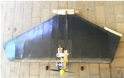
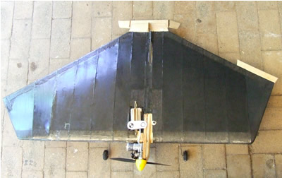
Here is the “Heart of Gold”, so modified. Note
the extra 100mm added to the outer panel, making that panel
75mm longer than the inner panel. See the extra lead sticky-taped
to the leading edge of the extended tip. Don’t blame
me for that, Dick Gibbs made me do it!
Above the tank, you can almost see the change in C/G so produced.
Too old and blind to see that? Ignore the trim tab on the
left panel; that’s an out-of-whack trim-compensator!
Now can you see it? The old C/G is the open circle, right
on the thrust-line, where it did no good at all apart from
giving level wings when upright and inverted.
The new C/G has the two black blade segments. It is 50mm
out-board of the thrust-line, where it has magic properties.
The tip weight has been chosen to balance the wing lift from
both panels, preventing roll-out. But that same amount of
tip weight has moved the C/G away from the thrust-line by
50mm, just what I wanted.
But why would I want that? Well, it is a law of physics that
free objects rotate about their C/G. The engine thrust-line
is now offset from the C/G, meaning that we have introduced
a yawing moment which was absent previously. In other words,
engine thrust is now trying to yaw the model out, thereby
increasing line tension.
The model will continue to yaw until the lead-outs, which
also have a yawing moment about the C/G, try to pull it back.
These moments at some point will be equal and opposite, at
which point the angle of yaw is fixed in space.
If we have the lead-outs well forward, as in the old Thunderbird,
then the yaw is a bit less than for more swept lead-outs.
So, big deal?
Well here is where it gets interesting. Say we lose some
line tension: then the inward yawing component provided by
the lead-outs is reduced. The offset thrust-line yawing moment
then dominates, so that line tension is restored as the model
yaws out!
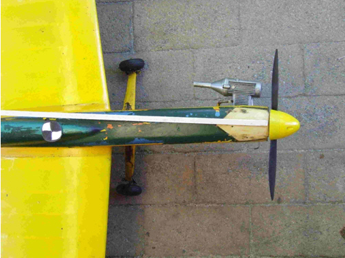
How neat is that! Automatic line-tension compensation! Here
is another photo to show how good is my new Fuji S5600 digital
camera.
Check out that lovely F2B prop on the Enya 45! Bet you would
love to have one of those! Only $35 from Supercool hisself!
Should go well with the offset C/G on your next stunter. That’s
right, the one with the longer outboard wing and heavier tip
weight!
Bet you’re not game! Oh, I forgot to say, this all
really worked on my test flights. The extra tension gives
extra precision, without the blinding speed of our top F2B
fliers.
Addendum:
I have received some response to this article, which goes
to show I have not lost my capacity for self-delusion, which
is encouraging! I repeat the responses below without {many}
changes.
From Preston:
I do visit your website regularly, of course. Phil Cartier,
an old combat flier, made much the same point about wanting
the CG outside the thrust line. I wanted to achieve this,
along with getting the centerlift right, by keeping the wings
the same length, but increasing the chord of the inboard tip.
Also by moving the engine slightly inboard, and adding a bit
more tip weight.
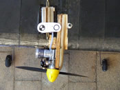
I'm not sure how clear it is, but look at the pictures here
http://www.clcombat.info/Images/x1/mounted.jpg
and here http://www.clcombat.info/Images/x1/Stab/DSCN1900.JPG
Nelson sells a magnesium back plate/engine mount that many
people use. I've rotated it 180 degrees, which serves to shift
the thrust line inboard 1/2 inch (bringing it 1/4 inch inside
the centerline versus 1/4 inch outside!). Otherwise, the engine
points straight ahead and the leadouts are set well forward.
Unfortunately, I smashed both examples pretty quickly, before
arriving at any conclusions about the flyability. I'll have
to build some more!
(I stole the idea of the larger inboard chord from Howard's
Son of Snort.)
From Bob:
Well, what you have done is just get REALLY good thrust offset.
Angling is good, but only when the engine is way out in front
of the CG. With the CG that far forward (“Heart-of-Gold”
160mm prop to C/G), it would take a huge angle to get the
same thrust moment arm about the CG. On a long nose stunt
airplane, an angular change will be a lot more effective.
I have not thought about CL issues much. Have not flown it
since I first got decent RC equipment 35 years ago! OTOH,
I think you need to sort out the two effect on the line tension.
First is the centrifugal force from the plane, but you also
have the air drag on the wires. When the lines go slack, the
first term goes to zero, but you still have the drag, which
gives an inward yawing moment.
Supercool-eats-crow:
As I said, age has not diminished my powers of self-delusion.
So I dragged out the old Firecracker, to see how much side
thrust I needed. With a nose moment of 400mm, I needed 3.6
degrees of side thrust to get 50mm at the C/G. That is still
less than I have on the “Heart-of-Gold”.
That is quite a lot of offset: I think the model construction
would need to plan for that angle. I only got that angle in
the photo by hanging the engine off of one bolt!
|

