| See the new article
More on cooling airplane engines
by reader Graham White
Advances in wing design, especially of F3D pylon
race models, have reached the point where further performance
gains may not be related to the surface configuration of the
model. If there is one area where gains may be expected, it
is in engine cooling.
On full-size aircraft, quite large gains in
performance have been achieved by reworking the cooling system.
I have in mind Roy LoPresti's work on the Mooney light aircraft.
From my memory, I recall he turned a 160 MPH airplane to a
201 MPH airplane, largely by reducing cooling drag. This seems
like an improbably large figure, so let us look more closely
at another example, this time not from memory.
In the magazine 'Aeroplane' for May 1999, there
is an article by the late Lee Atwood, vice-president of North
American Aviation in 1940, entitled 'We can build you a better
airplane than the P40'. The aircraft alluded to is no
less than the P51 Mustang , so we can expect some excitement!
Lee indicates that the propeller thrust at full
power was about 1000lbs. However, the drag of the cooling
radiator was of the order 400lbs! This is shocking,
nearly half the available thrust was required just for cooling
the engine. For you farmers out there, this is not unlike
using horses to plough and harvest your wheat fields: for
every 1000 bags of wheat, the horses eat 400! And that is
a fact!
By careful design of the radiator and its ducted
cooling system, it was possible to use the heat released by
the radiator to generate 350lb of thrust, thereby reducing
the net drag of the cooling system to just 50lbs. This was
a rather special achievement, possible due to the work F.W.Meredith,
in 1935, at the Royal Aircraft Establishment at Farnborough.
This reduction in cooling drag was mainly responsible for
making the Mustang some 30 MPH faster then the Mk IX
Spitfire, despite the higher critical Mach number of the Spitfire
wing.
There are a variety of opinions current on whether
it is possible to obtain thrust from the heat residual
of I/C engines. That is, the Meredith effect cannot be applied
, as the theory is simply wrong. Regrettably, I am too ignorant
of thermodynamics to contribute to this debate: however, I
believe there may be a book coming out on the cooling theory
for I/C engines so watch out for it. In the meantime, if you
are an expert and would like to contribute your view to my
website, I will happily place your comments here in this article.
Now here is food for thought. Perhaps our speeds
are too slow to use the Meredith effect on our racing models,
but just how bad is our cooling drag? Are our cowling designs
giving rise to more drag than, say, the wing itself? Highly
possible, based on those figures for the Spitfire and Mustang.
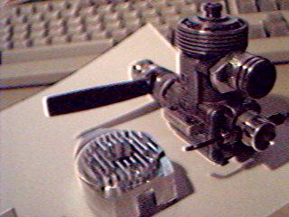
Recently I had the need to test my bar-stock
double-exponential tuned pipe on an OPS 40 mounted on my stationary
test stand. In characteristic Supercool fashion, things went
wrong very quickly. With the motor completely uncowled, air
rushing past it in all directions, I figured that cooling
was not an issue. How wrong can you be!
From cold, the motor would burst up on pipe
to 27000 RPM, then sag and sag down to 25700, and become impossible
to tune. Opening the needle did nothing. Getting pipe data
was impossible, so in set the Blues as my alter ego started
jabbing me with a pin and making me feel despondent. Was my
pipe at fault? I had heard of pipes burning holes in pistons:
was my 3 months of development and coding all wasted?
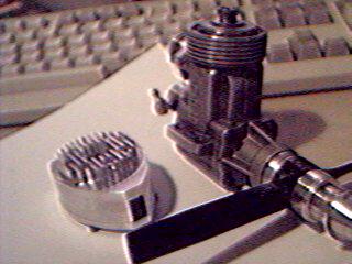
Looking closely at the engine, I noticed that
there was castor oil burnt onto the back of the cylinder,
offset slightly to starboard. This seemed to indicate excess
heating, or at least lack of cooling, at that point. Talking
to the C/L speed guru Grant, he spun me a wonderful story.
When dyno tuning his K&B 40 racing motor, he was able
to determine the cooling pattern from coloration of the liner
and piston. Cooling was fine in the front of the engine and
in the vicinity of the transfer ports, but not at the rear
of the cylinder in the region of the exhaust port. So air
was doing the cooling in front, and the fuel also contributing
to the cooling.
Cooling with the fuel mixture? This does not
sound so good to me. After all, the Spitfire had an intercooler
between the supercharger and the inlet manifolds, for the
express purpose of cooling the fuel mixture. Just the opposite
of what we are doing.
The MB40 pylon motor is well known for its heat
stability, especially on the starting line. Previously I thought
this may have been due to some wonderful metallurgy or the
elimination of the cylinder liner, the latter giving better
heat transfer to the cooling fins. But when I looked more
closely, I noticed that this motor has rear transfer ports
which can cool the rear of the cylinder, unlike the IR, Nelson
or RPM.
To my way of seeing things, the MB40 has never
performed up to my expectations. The front induction Nelson
and RPM have been able to keep pace, despite inferior design
specifications. Could it be that the MB40 has gained its temperature
stability from using the fuel to induce more uniform cooling
around the whole cylinder? If so, great for handling, lousy
for power. Hot fuel bad, cold fuel good.
Now back to my sad, obsolete OPS. If I was going
to test this darn pipe, I better cool the rear of the cylinder
so that, at least, the motor would hold a setting. But how
to do this? I didn't want to build a cowling for use on my
test stand, what a pain in the butt that would be. Everything
I do is conditioned by access to my CNC mill, and its enormous
power in sculpting shapes. Could I machine up a metal cowl
from bar stock, something that wouldn't flap around in the
breeze like composite cowlings are wont to do?
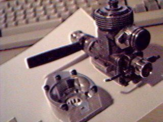
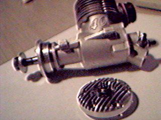
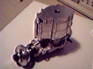
Then it hit me. My gloplug was held in place
by a clamp-ring, which also carried the head fins. What if
I was to machine up a new clamp ring, which retained the head
cooling fins, but included a shroud that dropped down over
the barrel cooling fins and forced the air round the back
of the motor! Piece of cake! Have it done Friday!
Well, it was Friday a month later I had it done,
and very racy it looked, too.
There are some principles involved in designing
a cooling duct such as this. I don't really understand them,
but I can regurgitate very well. We Australians are great
regurgitators, it assists with our beer drinking. It
goes like this. Blowing cold air at high speed over an engine
is a lousy way to cool it. Never mind that that is standard
practise, it is still lousy. The heat transfer is poor, and
the drag is very high.
The correct way to cool is to blow low speed,
high pressure air over the fins. This is standard practise
in full size airplanes, and if you know where to look, you
will find that this is true. But where do you get low speed,
high pressure air from? Well, chances are, if you look in
the front cowling holes on a Cessna or Piper, you won't see
the cooling fins. That is because the intake air is directed
by baffles into the top of the cowling, from where it moves
downwards thru the cooling fins, then out.
That chamber formed by the upper cowling is
called a plenum chamber: it has a wonderful property. Being
of large volume, the air that rushes in through the intake
holes is permitted to expand to fill the volume of the plenum
chamber. Now the magic part is that when air expands in the
fashion, its speed falls and its pressure increases! Wonderful,
just what we wanted, low speed air at high pressure.
So my OPS duct had to have a small opening that
expanded as much as possible to form a plenum in front of
the cylinder. Not much room there, but I was able to expand
it about 3 fold. Now that is a lot better than nothing, but
nothing like the expansion in, say, the Rare Bear cowling,
but I will return to that exotic later.
A baffle was incorporated in front of the boost
port to reduce excess cooling of the front of the cylinder,
as this would put the liner out of round just as much as overheating
the rear of the cylinder does. The duct then closed again
to force the low speed high pressure air around the cooling
fins, exiting at the pipe manifold. Not so good, I didn't
really want to heat the pipe manifold, but then these engines
are not really all that cleverly designed, so you must live
with it.
Now, where were we? Oh yes, the creaky old OPS
now had a cooling duct, which carried my hopes for further
glory. Yes folks, just in case you have missed the plot, this
is all about Honour and Advancement!
Well I fired up the OPS, and sat back to see
if the revs fell. No! Eureka! Over a period of thirty seconds,
the revs even climbed slowly from 27000 to 27300, and the
needle setting held! This was better than I dared dream.
Pipe temperature analysis shows that the tuned point rises
with the temperature, about 100 RPM per 10 degrees, and this
was where we were at!
Overjoyed, I fired up again. This time, the
motor burst into song and the head fell off! Yes, all 8 head-screws
took off in the slipstream and hid in the grass. Supercool,
you know that sorrow follows joy, fall cometh from pride!
I had torqued the screws lightly, as I always do, to allow
for the expansion of the alloy head against the steel screws.
But now the cooling was so great the screws were simply not
tight enough.
Unfortunately to this date I have not been able
to fly either the ducted head or the bar-stock pipe. But not
to worry, where to next?
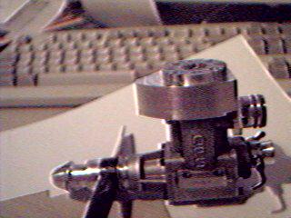
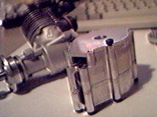
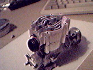
Well about this time a generous colleague in
the UK supplied me with an IR40, as being a bit more realistic
in performance compared to the 15 year-old OPS. The motor
was in perfect condition, beautifully made and appeared to
have been run very briefly, as it had light castor oil burn
marks on the rear fins, just in the same location as the OPS.
Click to enlarge
Right, I thought, now lets do this right this
time. Rather than smoking up this fine engine on my test stand,
I would fit it with a cooling duct before I ever ran it.
Not only that, I was finding the cost of plugs
a bit more than my poverty-level income could sustain. I do
enjoy food, it gives me energy: I prefer Testosterone pills,
they give me lust: but it was Honour and Advancement I was
after, not aching nether-regions.
So I drew up a new list of Specs for the IR
shroud:
-
Cool the cylinder fins with a deep shroud
-
Make the intake lips round to avoid poor
airflow at the intake
-
Provide the cylinder head with its own separate
duct
-
Provide the gloplug with its own cooling
duct
-
Improve the aerodynamics of the head cooling
fins to reduce drag
It is hard to imagine a worse design than the
head cooling fins on our racing motors. One would like to
think that the air would rush between those lovely head fins,
carrying away the heat and cooling the plug so it won't burn
out so easily. Well Mr Manufacturer, I suggest you stop spending
our money on Testosterone and start using your brains instead.
There is no way the air rushes between those
head fins. They have square ends, they are chopped into short
lengths for the head bolts, the head bolts stick up into the
fins and they have square exits. Aerodynamically, they are
hopeless. High speed, low pressure air rushes over the top
of the fins, producing high drag and poor heat transfer. Absolutely
woeful. Give me those pills, I use them for brain food!
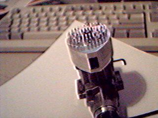
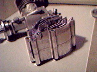
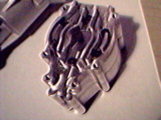
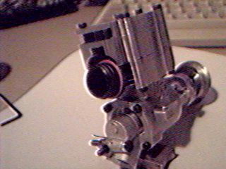
The IR head duct has the following features,
which I hope you can see in the photos.
-
The inlet end of the fins are rounded, and
the exit section tapers to a fine edge, simulating an
airfoil section.
-
The fins are curved, so that they pass around
the head bolts without interruption
-
The fins lie in a duct, which provides for
expansion to yield low speed, high- pressure air. This
in turn produces high heat transfer and low aerodynamic
drag by the fins.
-
The gloplug has its own duct, with its own
plenum and finning to cool the plug effectively.
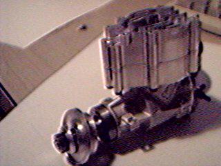
Admittedly, the whole assembly has the appearance
of a steam engine, but this is a developmental prototype.
There is much more that can be done to increase its efficiency.
For example, the slotted air- intake is quite the wrong design.
LoPresti, in his work on the Mooney, showed that the air intake
should be circular, with rounded lips. Not to kiss you with,
you Testosterone addled turkey's!
Now on the subject of lips, I promised to return
to Rare Bear. There is a lesson to be learnt from this mighty
Bearcat, just from standing on the ground and looking in the
cowling. Remember, this is a 530 MPH 3000+ horsepower
monster. The heat generated in one flight would warm my house
all winter. So just what does one see of the cooling
system?

Click to enlarge
Firstly, the air-intake is an annular slot around
the back of the spinner. It looks to be about 4' wide, which
isn't very much. The outer lip of the annulus is highly rounded,
to permit smooth flow of the air into the cowling of the air-cooled
radial engine. The air then enters a very large plenum chamber,
formed between the front row of cylinders and the forward
section of the cowling. The expansion must be very large,
I would guess a factor of 50, maybe more. So you see, this
engine is only going to see very slow moving, high-pressure
air at the cooling fins.
The flow of this air after it leaves the fins
was not apparent from the ground, but I would not be surprised
if the Meredith effect described earlier was in action. One
of the key requirements for the Meredith effect to work is
control of the back-pressure of the exiting air. This can
be provided by the variable cowling gills at the rear of the
motor. There is certainly plenty of heat available for generating
thrust!
There is yet more to say about the intake flow.
If the high speed air were not correctly ducted, it would
not expand smoothly to generate the high pressure air. It
is important that the fast moving air does not become turbulent.
That is also the reason that the P51 intake duct is stuck
out so far into the airstream: that prevents turbulent air
from the fuselage from entering the duct.
On the Bear, the smooth ducting continues from
the lip right up into the plenum chamber. Not only that, but
the crankshaft on the reverse side of the spinner is also
heavily faired, just as though there was a reversed spinner
backed up against the true spinner.
I have often wondered how aircraft like the
Bearcat, FW190, Thunderbolt, La-7, Lagg-3 etc, with radial
engines, were able to compete so effectively against aircraft
with liquid cooled engines, such as the Mustang, Me-109, and
Spitfire. These latter slender aircraft had in appearance
much lower frontal area. But appearances can be deceiving!
The aircraft that brought understanding to me
was the Fw190-D9. In appearance, this is a radial-engined
fighter. At least, it has a radial cowl, hardly what you would
expect to see on a liquid-cooled in-line engined fighter.
But the D-9 is exactly that! The engine is a Junkers Jumo
213A, a 12-cylinder in-line liquid cooled unit.
The radiators are mounted in the radial duct
in front of the engine, with the cowling gills immediately
behind the radiator duct. This is an even better set-up than
in Rare Bear. All the elements are there for a Meredith effect,
or at the very least for efficient low drag coolingÄ..low-speed,
high pressure air.
So if you have read those accounts of Kurt Tank,
the Fw designer, being bounced by Mustangs and simply flying
away from them, then perhaps the story is not so apocryphal
as it sounds. Which brings us back to the conundrum. How can
a big fat radial engined fighter compete on equal terms with
a slender liquid-cooled in-line engine?
The answer lies in the cooling drag. The physical
flat-plate area of the airframe comes a bad second to the
drag of the cooling system.
Well that just about wraps it up on ducted cooling.
All I have left to say is some more bad words to the manufacturers.
You are dragging your heels, you are out of date.
Future racing engines will be built with ducted
cooling systems, not the primitive stick-it-in-the-slipstream
rubbish we have now. Cooling fins will be aerodynamically
shaped and placed in plenum chamber ducts. Most likely, the
air intakes will be annular, like Rare Bear, and the fins
placed vertically on the crankcase to provide up-draft cooling
which exits above the pipe, not onto the pipe. The head and
plug will have their own ducts, with circular inlets. In this
way, fuel will no longer be used as a working fluid for the
cooling system. Power will rise, as the ducted cooling actually
cools the fuel in the transfers. Engine handling will improve,
as the uniform radial cooling of the cylinder maintains the
perfect circular shape of the cylinder. Plug life will increase.
Compression ratios can then be increased, and pipe stinger
exit diameters reduced, without risk of burning holes in the
piston.
And all this will be sourced back to Supercool!
Supercool, the father of the modern racing engine. Weep your
hearts out Nelson, Metkemyer and Phelan! If you are real nice
to me, I will even let you give me some engines and money
to develop your obsolete engines for you! Hurrah!
|