| The
method of Doppler analysis is described elsewhere
on this website . In a nutshell, the engine sound radiated
from a model in flight carries information which permits the
in-flight determination of airspeed and engine RPM. This information
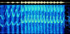
is extracted by analysing the sound via the sound card in
a computer, using physics first described by Herr Doppler
and a computer code written by Richard Horne which yields
the frequencies present in the sound.
Click to enlarge
The method has wide application,
most notably in F3D pylon racing and Control-line speed events,
which are both quite noisy events. However, the method, while
robust, does require corrections to be applied to yield quantitative
results, especially with respect to the airspeed component.F2A
in particular poses a challenge. With the models circulating
at one lap every 1.3 seconds (in your dreams!), the Spectrogram
code yields results which are somewhat distorted. So why should
this be?
The sound frequencies we
require for the analysis are those present when the model
is pointing directly at the microphone, and when it is pointing
directly away from the microphone. We call these values Fcoming
and Fgoing, for want of something better. In the case of F2A,
the amount of time this happens is measured in milliseconds,
not long enough for the sound sampling period of Spectrogram.
What does this mean? Well
in Spectrogram, one is required to make certain settings which
permit the program to work. In the case of F2A, these settings
are the Sample Rate (Hz) and FFT size (points). They should
be set to 11k and 2048 respectively.
Now with these settings,
it takes the program about 186 milliseconds to workout the
frequencies. In that time the model travels about 14 metres
and changes direction quite a lot. This means that the signal
we are trying to analyse has changed during the time of sampling.
In the case of F2A, this introduces an error of about 20 kph
in the Doppler-determined airspeed. That is not really cool
at all! We don't want that! In contrast , there
appears to be almost no error in the RPM result, so we are
half-way there!
Now lets do something Supercool.
Surely if we know what is causing the problem, then we can
do something about it? Yep, sure can. It works this
way. First guess the speed of the model. Then we can readily
calculate Fgoing and Fcoming just from the geometry of the
model trajectory, which we hope we know, although not always!
For each of these, we really need an average value over the
14 or so metres the model covers in the sampling time. If
we do this all around the circle, then we can figure out a
correction factor which is going to fix things up (we hope!)
Now from here on it gets
messy, all that maths and geometry, not much fun, either to
read or to write! No need to bother, all you really need is
the code. If you log in to my website, both the source
code and the .EXE files
are there, along with a sample Spectrogram. Now how good is
this code? Hard to know. But with a model doing about 280
kph, the new code gave a value of 277 kph. Not bad, that's
about as good as you will get from the Doppler method. Of
course, you get this lap by lap, which is really good to see
how steady is your motor run.
That's it, have fun, folks! |