|
In the first and second articles of this series, I have introduced
the notion that one can have immediate success in the design
of propellers if one already knows their design parameters
and performance. This method is like having 100% hindsight:
it is much better than thrashing around with complex equations
full of approximations and uncertainties. You know, garbage
in, garbage out.
Essentially, there is just one unknown in our
retrograde world: that is the angle of attack of the airfoil
to the undeflected free-stream. We need both this angle of
attack and the associated lift coefficient to complete our
“design” process.
For a brief historical diversion, it’s
worth noting that this is an “old” problem, being
sorted out prior to 1930. I can do no better than quote directly
from “Aircraft Propeller Design” by Fred E. Weick,
B.S., an aeronautical engineer from the NACA Langley Memorial
Laboratory, Virginia, USA, 1930.
“ In the application of the airfoil theory
to propeller blade-element analysis, the two-dimensional or
profile characteristics are used for the airfoil elements,
and the interference flow is calculated from the momentum
generated, after the manner of Froude and Rankine. Thus, since
only the profile lift and profile drag are used, the questionable
aspect ratio effect is eliminated. Also, since the interference
flow is determined by the number of blades, their spacing,
and the forces on each, the blade interference is accounted
for”.
Now that is a mouthful. Ignoring the Americanised
grammar, that says it all.
Says what?

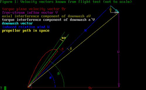
Figure 1
Refer to Figure 1. There are 3 angles shown
here:  , ,
 and
and  .
The first, .
The first,  ,
is the airfoil zero-lift angle, measured to the chord-line.
To obtain ,
is the airfoil zero-lift angle, measured to the chord-line.
To obtain  ,
I use the method of R.T. Jones, “Modern Subsonic Aerodynamics”,
1988: viz, ,
I use the method of R.T. Jones, “Modern Subsonic Aerodynamics”,
1988: viz,  = arctan(m/(1-p)),
where m
is the camber and p
the camber-line high point. This method agrees very well with
the more complex procedure given in Abbott and Von Doenhoff.
The second angle,  ,
is the angle of attack for an airfoil of infinite aspect ratio.
In the presentation of data for airfoils, with angle of attack
plotted against lift coefficient (the lift-slope), this is
the value that is presented. Just what it is in reality, we
may debate! ,
is the angle of attack for an airfoil of infinite aspect ratio.
In the presentation of data for airfoils, with angle of attack
plotted against lift coefficient (the lift-slope), this is
the value that is presented. Just what it is in reality, we
may debate!
The third angle,  ,
is the reduction in inflow angle due to the downwash.
If that makes no sense to you, just look on the diagram. It
still won’t make sense, but at least you know where
it is. ,
is the reduction in inflow angle due to the downwash.
If that makes no sense to you, just look on the diagram. It
still won’t make sense, but at least you know where
it is.
Now at this stage, we are following the vector
diagram given by Larrabee and others quite well. But what
it all means is by no means clear. Recall, we are trying to
find the angle of attack to use with our expression from Part
2, viz:

The terms a'
and W
in the above equation are dependent on the angle of
attack, if we only knew what angle we are talking about.
Now as it happens, Larrabee says this: “The
necessary geometric angle with respect to the undisturbed
air is obtained by adding the induced angle of attack to the
theoretical angle of attack required for a wing of infinite
span in two-dimensional (Joukowsky) flow." (Scientific
American, July 1980, “The Screw Propeller”)
OK. That settles the matter. Now it’s
all clear. Right? From our diagram, just add  and
and  .
But to do what? Weick tells us to get Cl
from the two-dimensional data, namely using .
But to do what? Weick tells us to get Cl
from the two-dimensional data, namely using  only. Maybe we need a diagram. David Rehm’s article
“Understanding Airfoil Data”, the Experimenter
via Pacific Flyer, March 2004, is a good start for further
reading. Blame him for the following.
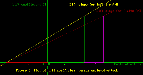
Rehm states: “When the wing is at zero-lift,
this is the one and only point where a 2-D wing (ed: infinite
aspect ratio) and a 3-D (ed: finite aspect ratio) wing will
behave the same…they will both produce zero lift. Start
pitching up with a 3-D wing and the lift slope will rotate
downward (ed: see my Figure 2). The important factor is that
they rotate about the point where they cross the horizontal
line at zero lift coefficient”
The above statement by Rehm allowed me to draw
Figure 2. All I had to do was take the point at (
- ,
0)
and rotate the lift slope clockwise to form the lift slope
for an airfoil of finite aspect ratio. This is a legitimate
lift-slope, which we can construct for our guessed values
of ,
0)
and rotate the lift slope clockwise to form the lift slope
for an airfoil of finite aspect ratio. This is a legitimate
lift-slope, which we can construct for our guessed values
of  and
and  . .

Figure 2
We required the guessed values to give us our
design lift coefficient. Now it can be seen that this value
of lift coefficient is achieved when Cl
for angle-of-attack  for infinite as aspect ratio lift slope is the same for the
finite aspect ratio case when the angle of attack is
  +
+  . .
Therefore, it makes no difference which lift
slope we use. However, the only data we have is for the lift
slope data for infinite aspect ratio, so I guess that means
we have no choice.
There is an interesting corollary to all this.
Some folks like to say, look at that long thin prop, it must
have a high aspect ratio. Good point.
Using the definition that converts low aspect
ratio (A/R) data to infinite aspect ratio, we can show that
for a given blade element,

|