| It
is now one year since I wrote Acoustic Antenna Part 1. The acoustic
antenna is intended to follow the path of any non-muffled engine-powered
model by means of an array of 8 microphones. The signals from these
mikes go into a computer, which computes the phase difference between
the mikes and hence hopefully determines the trajectory, in three
dimensions, and airspeed.
In that article, I
indicated that the computer sound card was a good prospect for use
as a multi-channel very fast analog to digital converter. After
initial success installing two sound cards and reading 2 microphones
via Quick Basic commands, my efforts were crowned with the thorns
of failure. When Windows wasn't actually crashing, it seemed to
be fighting all my attempts to read the line-in and microphone channels
separately. It's a long story, but basically I gave up.
Until, that is, I
had a chat about my problems with Stuart Maxwell. Stuart's idea
was for me to provide my own analog to digital converter, and read
it into the computer via the ISA bus. If you look inside your computer,
you will find some cards plugged into various slots: these are the
ISA and PCI card slots. The PCI slots are difficult to address from
Quick Basic, but the ISA slots are simplicity itself.
Only two commands
are required, OUT and INP. OUT writes a byte onto the ISA port,
and INP reads a byte off the ISA port. Now all you need is something
to OUT and INP to! As it happens, there was published in Electronics
Australia November 1996 the details of a construction project called
"Improved 24-line I/O card for PC's". This card plugs
into the ISA slot, and loves nothing better than receiving some
OUT and INP commands. Hence it is ideal for controlling an analog
to digital converter (ADC) such as the 7822 produced by Analog Devices
(www.analog.com). What is needed then is a microphone signal which
one requires to feed into the computer.
I have been using
microphone kits from Oatley electronics, and these worked fine,
especially with the Dick Smith pre-Champ amplifier. However, the
acoustic antenna is required to detect sound from the model when
it may be half a mile away, or up close; such is the range of sound
level that this may be difficult.
In using Doppler effect
for measuring RPM and airspeed, I was using Digitor tape recorders,
and found that they did very well at picking up the weak sounds
from a very distant model. They contain a device for amplifying
weak sounds and at the same time not overloading on loud sounds.
This is an Automatic Gain Control (AGC); I needed one badly.
So I was pleasantly
surprised to find a suite of chips on the ANALOG web site, which
included a microphone preamplifier with a built in AGC. This sounded
ideal, a purpose built device for my application: perhaps the fates
were smiling on me at last. Also in the suite were line drivers
that would enable me to send the signal from the antenna to the
base computer, up to 1000 feet away. How could I go wrong? Little
did I know.
Firstly, I tried to
order these chips from the local suppliers. These rascally resellers
were asking so much money for the chips I literally could not afford
to buy them. They were asking up to 4 times the US list price, for
chips sold in the USA as "economically priced". So I purchased
them in the USA, and landed them here at half the local price, except
for the ADC's, which they threw in for nothing! So far so good.
Chips in hand, I proceeded
to build a single channel of the antenna, comprising an electret
microphone, SSM2165 microphone preamplifier and SSM2142 line driver.
It all worked, except for one thing. It was nearly deaf: I had to
shout for it to hear me, and then it had only a small signal output.
No problem with the output, I could easily boost that with a 741
op amp.
However, this thing
seemed to need an amp in front of the preamp! Hell, thats nuts!
On reading further the spec sheet, I realised the chip included
a non-adjustable input signal threshold of 500 microvolts. Doesn't
sound like much, but the microphone produces at best about 30 millivolts,
which is also not much. OK, I could live with an amp in front of
the preamp, but then I found that the AGC was pretty hopeless as
well.
Now you may think
I'm a bit of a fussbudget, just because the SSM2165 is a hopeless
chip. But its worse than that. The chip is whats called a surface-mount
chip. It is half the size of a regular DIL chip, and the pins don't
line up with VERO board. So before I could even mount the chip,
I had to pay out several hundred dollars to have made some tiny
circuit boards to convert the surface mount to match my boards.
Not so much fun now, is it?
I had been on the
look out for several years (unsuccessfully) for an AGC circuit.
I asked everyone in sight, with no joy at all. Then I met a guy
who suggested one could couple two circuits together using an LED
on one and a photo resistor on the other, and this could be made
to work as an AGC. Fair enough, I'll give that a go.
Then I remembered
the Laser Communicator I purchased from Oatley Electronics some
time ago. It had LED's and photo resistors, so I dug out the circuit
and what did I find? A beautiful AGC right there on the transmitter
board. As it happened, it did not use the LED/photo-diode set-up,
but a FET in the feedback loop of the microphone. With nothing to
lose, I pulled off the 2165 and built the whole laser front-end
onto my board.
Instant gratification!
The thing detected the sound of my breathing, and didn't overload
when I yelled at it! It turns out that this circuit is very similar
to that found in tape recorders: at last I was on to a winner.
This left only to
fire up the ADC. I built it onto VERO board, using 1 byte on the
I/O card for reading the data using INP, and 1 byte for controlling
the ADC read/address requirements using the OUT command. Since I
need eight microphones sampled simultaneously in the antenna, I
needed a 3 of 8-decoder chip, a 74138.
The board didn't work.
Not again!! I was baffled, and by now my sound card based oscilloscope
was no longer up to the task. I pulled out my SoftMark oscilloscope
card and it didn't work either, so it was off to Altronics to buy
a nice 2-channel Hung Chang oscilloscope. Now we were cooking with
gas! No food in the house, mind you, but now I could see what I
was doing. And what I could see wasn't pretty.
Part of the circuitry
required for the ADC is a level shifter. I built it from the Analog
Devices circuit diagram, and it didn't work. By now I was beginning
to think I was dealing with Microsoft rubbish, but no, this was
the mighty Analog Devices. And their circuit was simply wrong.
But they got one thing
right. Yes, the disclaimer. There in the corner of the sheet, "
Information furnished by Analog Devices is believed to be accurate
and reliable.....". Why do they think it is accurate and reliable?
They clearly never built and ran the circuit! Is their disclaimer
based on a revelation from the divine?
Well, with everything
fixed, patched and redesigned, the channel now works, as a prototype
anyway. There is noise on the ADC, probably the result of the high
inductance of the VERO board layout. Sadly, VERO wiring kits, which
produce very low inductance circuit layouts, seem no longer to be
available. Indeed, I haven't found anyone old enough to remember
them. So I shall have to make my own, which means back to the injection
moulder to make the wiring combs.
Performance of the
system is looking very promising. I am getting over 100,000 samples
per channel in Quick Basic, and over 200,000 samples per channel
in Power Basic. This should yield excellent spatial resolution for
the antenna, for models doing up to 300 MPH. Yes Yes Yes!
Lets hope its not
another year before the next epistle. Cheers from Joe Supercool.
Photo
Description |
Link |
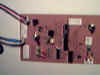
| 8-bit ADC board
layout for low inductance wiring. Very fast ADC chip permits
digitisation of signal from microphone. |
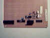 |
| Vero board circuit
test layout for ADC. ADC conversion time of order 2 microseconds. |
 |
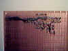
| Reverse side of
ADC board layout for low inductance showing wiring dress. Wiring
is wire-wrap hook-up wire, soldered to pins. |
 |
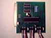
| I/O card plugs
into ISA slot on computer motherboard. Permits computer to control
address and reading of the ADC card. |
 |
| LED circuit which
permitted easy testing of the I/O card. I/O card is not conspicuously
easy to program. |
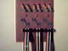 |
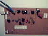
| Analog card provides
the acoustic antenna transducer. Excellent AGC circuit from
Oatley Laser Communicator kit. |
 |
|