| Well folks, hope
you have read Part 1.
Just in case you have not, here is the story so far.
Propeller tip speeds can easily exceed Mach 0.7. When they
do, the air flowing over them does weird things. I mean even
weirder than below Mach 0.7, so that is pretty weird indeed.
The main weird thing that happens above Mach 0.7 is that shock
waves start to form on the airfoil upper surface: at even
higher speeds they appear also on the lower surface.
These phenomena give rise to something that appears to be
complete nonsense. The airfoils actually work better if they
are upside down. No joke, they really do, and props I have
made with this feature (negative camber) actually do work
better.
Now it turns out that while turning the airfoil upside down
is good, we can do better. The extra improvement is achieved
by modifying the way the shock waves form. So first we had
better observe these weird waves a bit more closely.
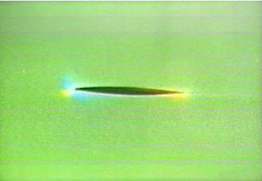
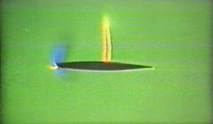
Above, a biconvex airfoil is operating below Mach 0.7, at
a low angle of attack. The blue region at the leading edge
shows low pressure, and yellow is high pressure. Make a mental
note now of the yellow region below the trailing edge. We
are later going to try and enhance the size of this region
in an effort to generate extra lift when the flow goes transonic:
such an enhancement we will call “rear loading”.
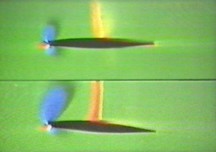
Now let us look at the same airfoil (below), this time with
the flow strongly in the transonic region. This time a strong
shock wave has formed. Behind this wave, the flow has suddenly
slowed below Mach 1: the pressure and temperature have increased
suddenly and the flow may be turbulent. If you have ever lap-swum
in the turbulent wake of another swimmer, then you will know
that this air is not much use for making lift.
At the leading edge, the blue areas again indicate low pressure.
This low pressure arises as the air from the stagnation point
(in yellow, at the leading edge) increases in velocity as
it wraps around the leading edge. Unfortunately, it then goes
supersonic from there all the way to the shock wave, which
means there is little or no lift produced in that region.
Things are not looking good for this airfoil, but they can
get worse! Below, the flow has speeded up some more: the flow
on the undersurface has also gone supersonic, with the result
that we now have a lower surface shock as well! As far as
using this airfoil for a propeller tip, we might as well give
up now and go home.

But just for the moment, lets assume this airfoil was giving
some useful lift. Then we might want to run it at a higher
angle of attack. Let’s see what that does.
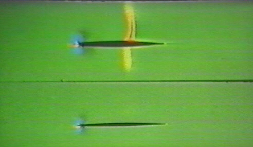
In the figure below, we can compare the shock formation at
low and high angles of attack. Unfortunately, all we have
done by increasing the angle of attack is make the shock that
much stronger. There is a possible gain in lift from the leading
edge low pressure, but the drag rise from the strong shock
we could do without.
This is all getting rather depressing. Is there nothing we
can do to fix this horrid set of conditions? Well, lets try
a thinner airfoil and see if that helps.
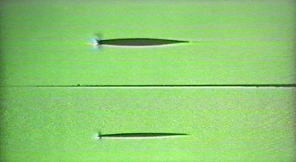
Here (above) we have 2 airfoils, one thick and one thin.
Or, as they say in New Zealand, land of the lost vowels, one
thuck and one thun. At a Mach number less than 0.7, they seem
to be behaving. Now we will speed up the flow to the transonic
region.
Perhaps that was not a good idea. The thick airfoil has gone
berserk, while the thin airfoil seems to be unaffected by
the speed increase. Aha, perhaps this is why Abbott and Von
Doenhoff conclude that transonic airfoils should be thin and
symmetrical!
Or maybe not, how would I know what other people think. But
perhaps we can say something along these lines below.
Shock waves form on the upper surface because the speed of
the air over that surface exceeds Mach 1. If we could slow
that upper-surface air down a bit, we could reduce the strength
of the shock. As seen on the thin airfoil, reducing the curvature
of the upper surface (thereby reducing the speed of the air)
reduces the strength of the shock.
Make a mental note now. We are going to make an airfoil that
is nearly flat on top. That is what happened in Part 1 when
we turned NACA 3409 upside down to make the eggfoil -3409.
OK. Now where are we? Well, we’ve had a look at some
shock waves and how they affect the transonic region between
Mach 0.7 and Mach 1.
Also we have made 2 mental notes. In case you have forgotten
already, the first was that we were going to modify the airfoil
to produce lift at the trailing edge under-surface by “rear
loading”.
The second is that we are going to flatten off the upper surface
to reduce the strength of the upper surface shock, which appears
to be the main bogey man.
Now for a little abstraction. Below the speed at which shock
waves form (the so-called “critical Mach number”),
lift on an airfoil arises from reducing the pressure on the
upper surface (suction side), whilst also increasing pressure
on the lower side (pressure side). Most of the lift from this
arrangement is generated on the suction side, the pressure
lift being much less.
Now we have just seen 2309 that this set-up does not work
above the “critical Mach number”, where shock
waves start to mess up our lovely air-flow.
Where we are heading is this. We are going to give up on
the suction side of the airfoil: just make it pretty flat,
and hope to eliminate the nasty upper surface shock. On the
lower surface, we are going to do 2 things. The first is to
increase pressure lift at the rear undersurface of the airfoil:
the second is to weaken the lower surface shock
This is quite radical. Switching from suction lift to pressure
lift is really quite novel. As far as I can tell, it was only
in the early 1970’s that airfoil designers started to
think this way for the transonic region. This despite the
revealing data already known to NACA in the late 1940’s
and published widely by Abbott and Von Doenhoff in “Theory
of Wing Sections”.
OK. Strike up the band, its time to enter the dance floor.
Now we really start to swing to the tune of “Dance of
the shock waves”.
Focus on the diagram above. Use the left eye to examine the
diagram, the right eye to follow this text.
Running from top to bottom, the trailing edge is progressively
drooped, what I call a “cusp”. As this happens,
the upper surface shock moves back toward the trailing edge.
The lower surface shock moves forward and disappears.
Now ain’t that cute! The dance of the shock waves!
I guess we should make a stab at just what weirdnesses are
happening here.
Well I guess the effect of the cusp is to speed up the air
over the upper surface, thereby moving the shock back.
Likewise, the effect of the cusp is to slow the air on the
undersurface, causing the lower surface shock to move forward
and TO DISAPPEAR altogether! Now we are cooking with gas!
We didn’t want that lower surface shock, and here we
have it disappearing altogether. Mate!!! What is more, that
subsonic air under the cusp has increased in pressure, giving
us “rear loading” effect, thereby boosting lift
on the pressure side! Eureka!
What with having already reduced the strength of the upper
surface shock by flattening out the upper surface, we have
got ourselves a really nice transonic airfoil.
But is this all true? Or just another Supercool aberration,
what with the war going on between his left lobe, right lobe
and imminent senility?
First off, where on earth did that diagram come from? Well
I would have given you photos from my transonic wind tunnel
(fantasy) but I couldn’t capture good frames from my
video. The tunnel set-up was an aileron going up and down
rather fast at Mach .9, so while I could see the dance of
the shock waves taking place, I just couldn’t get clear
pics. A secondary shock forming at the aileron hinge point
didn’t help either. So I have faked up the above diagram
to make things clear.
What isn’t faked are test flights we have done with
these airfoils in F3D and F2A models. Both these classes have
propeller tip speeds close to Mach 0.95, so we are really
in a very bad way if we get the airfoils wrong. Fancy tip
plan-forms won’t fix this problem!
Well, in F3D we picked up 15 kph in the straights, and 5
kph in the turns. In F2A we picked up 11 kph, to jump from
284 to 295! Change your undies Paramon, here we come!
Finally, Supercool has these props for sale at a premium
price to selected rich guys. Price on application. Cheers.
|