| Read the recent
comment on this article (March,03)
This months hot topic is propeller tips, literally.
Normally the shape and airfoil of propeller tips is not of
much interest, as they don't much affect performance. However,
in some racing classes the propeller tip speeds approach that
of sound. This introduces a whole new realm of aerodynamics
and the profile of the airfoil section becomes very critical
indeed. These classes include F2A and F3D, with F2A the most
critical of all.
There is one piece of jargon that cannot be
avoided, that being the Mach number, denoted by M. If we have
a situation where the speed is 340 m/s, then the Mach number
is defined as 1. Since this is the speed of sound, an aeroplane
flying at this speed is doing Mach 1. At half this speed,
say 170 m/s, the Mach number is, by simple proportion, Mach
.5.
To get anywhere, we need to be able to calculate
the propeller tip Mach number. Firstly we need the speed of
sound, Mo, which is a function of air temperature alone. With
the air temperature denoted by T in degrees Centigrade:
Mo = .594 * T + 325.56 , the units being metres/second.
The propeller tip speed Vr due to rotation alone is given
by:
Vr = .00010472 * RPM * R m/s
Here, RPM is revs per minute and R is the propeller radius
measured in millimetres. When the airplane is at full speed
V (m/s), the speed of the air over the propeller tip is increased
above that due to rotation alone. The "helical" tip speed
in flight Vtip is obtained by adding the airspeed V to the
rotation tip speed Vr using the rule of vector addition, viz:
Vtip = SQR( Vr ^ 2 + V ^ 2 )
where SQR means square root and ^ 2 means squared.
The tip Mach number is then just:
M = Vtip / Mo
, with no units at all, ie, M is non-dimensional. Consider
an example from F2A, with a 75mm radius propeller of unmentionable
origin. Lets say you do 300 k/hr (83.333 m/s) at 38000 RPM
on a nice sunny day in WA, when T = 40 degrees Centigrade.
Then:
Mo = .594 * 40 +325.56
= 349.3 m/s
Also,
Vr = .00010472 * 38000 * 75
= 298.452 m/s
and
Vtip = SQR( 298.452 ^ 2 + 83.333 ^ 2 )
= 309.87 m/s
Finally,
M = 309.87 / 349.3
= .887
The question now is whether a propeller tip speed of M = .887
is something to give us pause. If the Mach number was less
than M = .7, we could just forget it, as with most useful
airfoils the performance is OK. But above M = .7, awful things
start to happen. For a start, the noise produced by the airfoil
at the tip starts to rise very rapidly. But much worse, the
lift may fall, also very rapidly. If the airfoil thickness-to-chord
ratio (t/c) is above 15%, then at M = .887 the lift of the
tip airfoil can actually be negative. That is, the tip is
actually pushing backwards ! This is weird, demanding explanation,
at least if you want to go fast. By reducing t/c to something
like 7%, this problem is overcome, the tip airfoil again providing
satisfactory lift.
There is something about t/c that is important
at high Mach numbers. You cannot use wing type airfoils for
high Mach number propeller tips and expect to get good results.
Clark Y, for example, is no good unless thinned right out.
The aerodynamic problem is that, above M = .7, shock waves
start to form and become stronger as speed increases further.
Accompanying the shock wave are increased drag and reduced
lift, due to turbulent airflow behind the shock. You may have
seen these shocks yourself, when travelling in a jet airliner.
Modern jets have best range when flying at a speed which produces
a mild shock wave on the wing surface.
If you look out the window, you should be able
to see a shadow on the wing surface, just like a thin line
reaching from root toward the tip for a few metres. The line
may be a centimetre wide, and be moving erratically fore-and-aft
a few centimetres as turbulence affects the velocity over
the wing. The shock exists at a point where the airflow reduces
below the speed of sound. Forward of the shock, the airflow
has high velocity and low pressure, while to the rear of the
shock the airflow has reduced velocity and increased pressure.
The shock wave itself is a thin planar surface, less then
.1 mm thick.
|
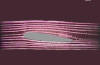 |
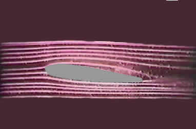
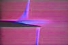
Flow
pattern around an airfoil section at low speed. No
shockwave present. |
|
 |
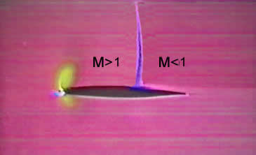
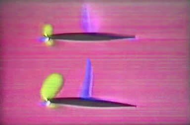
Flow
pattern at high speed, about M=.7. Air speeding
over the curvature of the wing has exceeded M=1
in front of the shockwave, and drops below M=1 behind
the shockwave. Also shown in blue are reduced pressure
regions at the leading edge, and a yellow region
at the leading edge showing compression at the stagnation
point. |
|
 |
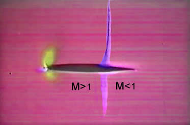
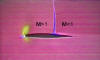
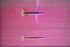
At
still higher speeds, a shock wave also forms on the
lower surface. Again, the flow in front of the shock
is supersonic, and behind, subsonic. |
|
 |
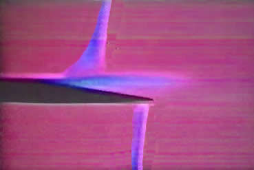
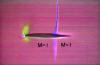
Even
faster, and the shockwaves have moved rearward. Lift
is lost due to shock-induced flow separation on the
upper surface near the trailing edge. |
The point is, that once shock waves form they
dominate the characteristics of the airfoil. Most airliners
have very thick wing roots, to provide strength and somewhere
to store the undercarriage: you would expect shock waves to
form on these thick wing roots, as the air must be speeded
up considerably to get over them, and hence be solidly supersonic.
However, the designers dodge this in 2 ways.
Firstly, they add an extension to the trailing
edge at the wing root, so that the inboard wing planform is
almost a delta: there may be little or no sweep on the inboard
trailing edge. This trick reduces the thickness-to-chord ratio,
thereby limiting the airflow velocity increase over the roots,
and avoiding the shocks.
Secondly, they build the airfoil upside down. No joke, look
for yourself next time you're at the airport. We noted above
that that some airfoils lift downward at high Mach numbers:
it only stands to reason that they will lift upwards if you
turn them upside down !
Designers only started doing this in the early
1970's, even though data were available in the 1950's which
suggested this course of action. To cover their a...s's, they
called the new type wings "supercritical wings" and the airfoils
"supercritical sections".
There is of course nothing "critical" about
them at all. This word arises from the "critical Mach number",
which is the Mach number at which the shock wave starts to
form on a given airfoil. The associated rapid change in characteristics
is called "force divergence".
To be fair, there is some additional sculpting
of the section to spread the lift force over most of the chord,
and to delay the upper surface shock so that it occurs at
the same speed as the lower surface shock. This raises the
critical Mach number even higher, yielding more speed and
better range .
We must now return to propeller sections. In F2A and F3D,
the tip speeds routinely exceed the critical Mach number of
conventional lifting sections, often by a considerable margin.
This is disastrous. Propeller efficiency falls hopelessly:
all that engine power you worked so hard to get is wasted
just by overcoming the tip drag caused by shock waves.
|
 |
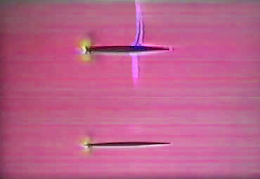
Comparison
of "thick" and "thin" airfoil
sections at the same Mach number. The thick airfoil
forms shockwaves before the thin section. Thus
thin section have lower drag at high speed. The thin
section is said to have a "higher critical Mach
number" In crossing the shock wave, the
air becomes heated, and its pressure increases. The
energy lost in this manner is not available to produce
lift and is thus wasted. This means that
a propeller tip running at high Mach number wastes
a lot of energy that would otherwise go into making thrust. |
|
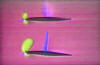 |
When
the angle of attack is increased, shock waves occur
earlier. Thus at high Mach numbers the amount of lift
available from the airfoil is limited. |
It is the fashion these days to rake the blade
tip over the last few millimetres into a scimitar shape. This
certainly raises the critical Mach number,in just the same
way as does sweepback: but it does little for the lift, or,
more importantly, for the lift-to-drag ratio. The problem
is that the resultant very narrow tips have lower Reynolds
numbers, producing poor flow characteristics that reinforce
the poor high-Mach airfoil performance.
You just can't beat wide chords for good airfoil
performance.
So where does this all leave us? For M > .7, you need:
1. Squared off tip planforms
2. Supercritical airfoil sections
In Britain, in the early 70's, the Aeronautical Research Association
produced a new family of airfoils specifically for propeller
use, and called them ARA-D. Likewise, in the early 80's, Grumman
Aerospace, using advanced computational aerodynamics, developed
their M series sections. The ARA-D sections are a single parameter
family, based solely on t/c. Since, as we have seen earlier,
t/c must be chosen to suit the Mach number, it follows that
the ARA-D family depend also on Mach number. See the attached
drawings.
Insofar as propeller tip airfoils are concerned,
the ARA-D section for M = .95 is very thin (3% t/c) and highly
cambered (5%). The leading edge is well rounded and the trailing
edge cut off-square. Compared to most model use, this is radical.
The camber high point is well forward at 10% for low Mach,
moving back to 30% for high Mach.
Empirical model propeller tip sections are
thin (6%), have low camber (are symmetrical) with sharp leading
and trailing edges. The high point is commonly at 40%, irrespective
of Mach. It is probable that these sections are quite inappropriate
for F2A and F3D.
The problems are:
1. Low camber sections have low lift to drag ratios. That
is fine for a wing in a dive, but no good for a propeller
section which must always produce high lift.
2. Sharp leading edges promote flow breakaway with rapid changes
in angle of attack. During a single rotation of a propeller,
angle of attack changes occur rapidly due to inflow variations
caused by the presence of the airframe behind the propeller,
manoeuvering and engine induced vibration.
3. Sharp trailing edges do not enhance flow re-attachment
at high Mach numbers.
4. Rearward high points produce lower maximum lift.
The ARA-D sections overcome these objections. In addition,
they delay shock formation, featuring high lift-to-drag ratios
at high mach numbers.
Model-wise, they are difficult to reproduce, and have high
variation in zero-lift angle, requiring greater care in setting
the pitch angles. These latter objections are overcome only
by using sophisticated CAD/CAM production methods. Despite
this, it pays to make the section as thin as possible and
maintain some camber.
However, it is quite likely that significant
performance gains may be had from use of sections. Chances
are, what you'll see is essentially a cambered flat plate,
similar to the airfoils shown here.
Finally, you may wonder how we do as well as
we do if all the foregoing is true. There is end of the blade,
it is affected by the 3-dimensional flow associated with the
tip vortex. This type of flow delays the formation of the
shock wave. As a rule of thumb, airfoils at propeller tips
think the tip speed is .05 Mach less than it actually is.
Thus, if we computed above that M = .887, then the tip airfoil
thinks it sees M = .837, which is a bit better situation.
Comment
on this article from Larry Lipera
Stuart,
Interesting article. My comments are the following:
1) I haven't seen an airfoil that produces negative lift at
positive angle of attack. As Mach number is increased, the
lift-curve slope (lift vs angle-of-attack) actually increases
up to the critical Mach number, then drops off. After Mcr,
all sorts of weird things happen that are highly dependant
on the specific airfoil, so I wouldn't discount the idea entirely.
But even though lift increases with M, drag goes up a LOT
(thus lower L/D).
2) Thick airfoil sections can reach Mcr even at M=.6, or below.
We design our airfoils to operate at a Maximum of Cl=.6 or
.7 because of the lower Reynolds numbers. At low Rn, max.
lift decreases; airfoils that stall at normal Rn at CL=1.3
stall instead around 0.8 at low Rn.
3) Airlines utilize wing sweep to delay Mcr. In fact, the
l.e. of the root sections sometimes fair into the fuselage
such that the sweep is higher than the main wing. Root sections
have always been a pain-in-the-a*s for aerodynamicists. Low
wing aircraft require fancy work at the root to make up for
their inefficiencies - mainly the effect of the fuselage boundary
layer on the top of the wing. High wings are much better in
this respect. But in terms of shock waves, this is exactly
the reason that Witcomb used the 'area rule' - to decrease
the shock wave interaction.
4) Maybe I'm too conservative, but its probably best to avoid
M>.7 entirely instead of trying to design around it. Lower
the rpm (if possible), and increase the blade area. |