| Back in the early
1800's, when I was just a lad, Herr Doppler discovered that
when a locomotive hauling a load of trumpet players went past
the station, the tone of their instruments changed from high
to low pitch. Thus was the Doppler effect discovered.
More recently, at the Reno heavy metal air-races, I noticed
that when Dago Red was comin straight at ya, the Merlin sounded
like a swarm of bees, and really screamed. But once it went
past, it sounded like my mother beating the carpets, a real
clatter but not much force. At 450 MPH plus, the Doppler effect
is easily observed. What has this to do with propeller design?
Well, you can't really design a propeller without knowing
the RPM and airspeed. Most of the time you do not know these
two factors, and it drives me nuts. I have produced some beautiful
props based on bad data, and lost a lot of money over it.
So when the possibility of measuring these factors arose,
I jumped at it.
This is the sequence of events.
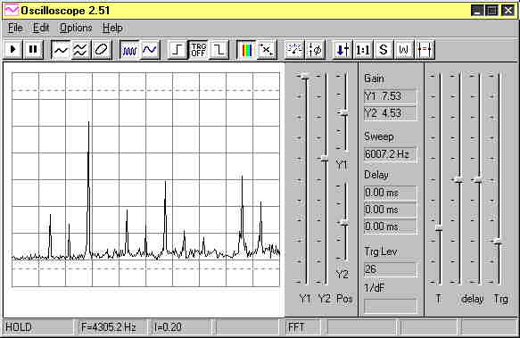
Firstly, I discovered that the sound card (Creative Sound
Blaster AWE64 pnp) in my computer (Pentium 100) could be used
as a virtual oscilloscope. Not only that, but Konstantin Zeldovitch
had written software (Oscilloscope 2.51) that included a real
time spectrum analyser! ( PC World October 1998 CD). Now if
you wonder what is so exciting about that, let me tell you!
The audio spectrum from a model engine/propeller is comprised
of a set of harmonics, which you can see in the accompanying
diagrams. The frequency spacing of these harmonics are all
the same, and are just equal to the revs per second. Just
multiply by 60 and you have the RPM! Is that not magic?
Secondly, I found in Electronics Australia for August 1998,
a circuit for a Sound-card preamplifier, designed just for
use with Konstantin's program. This was available as a kit
from various suppliers, including Jaycar and Dick Smith. So
I bought one from Jaycar for about $30, built it and had myself
an audio analyser. I believe the Dick Smith version includes
the software, so it may have been a better deal. I modified
the kit slightly by putting a 3.5mm mono socket in parallel
with one input. This was to match the monitor (head-phone)
output socket on my Panasonic mini-cassette recorder RQ-L309.
Then it was off to the flying field to record GT's F3D pylon
ship on the tape recorder.
Back home, I hooked the recorder to the Pre-amp and fired
up the audio analyser. What a sweet set of harmonics were
on that tape! While playing the tape, I had the sound of the
engine on my speakers and the frequency spectrum on my computer
screen. It was thus an easy matter to tell whether the model
was coming or going, especially as I made voice notes on the
tape at the time of recording.
Now take a look at the diagrams. Down the bottom of the first
one you will see written F=4305.2 Hz. That is the frequency
of the tenth harmonic. Just divide by ten to have the revs
per second, and multiply by 60 to get 25800 RPM. That is with
the model stationary on the ground prior to launch, so lets
call this the static RPM.
Those spikes on the diagram are the harmonics. If you can't
see that they are equally spaced, don't worry. Sometimes artefacts
occur which prevent some harmonics appearing. You just have
to imagine them in place, as they really do exist. The height
of the spike does not matter, only its position.
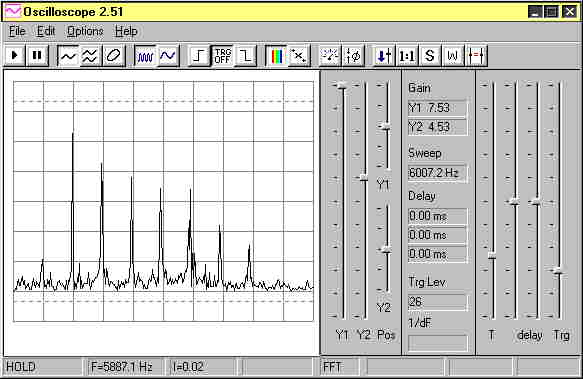
In the next diagram, you see F=5887.1 Hz at
the bottom. This spectrum of harmonics arose with the model
approaching the tape recorder at nearly 200 MPH. This value
of F corresponds to 35300 RPM, but this is misleading. As
for Dago Red, the frequency seems high due to the motion of
the aircaft.
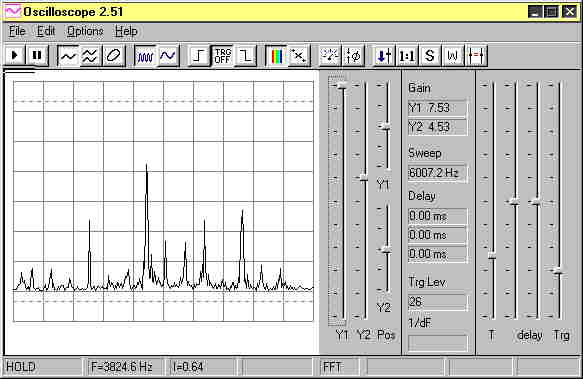
The third spectrum, captured after the plane
has gone past, has F=3824.6 Hz, or 22900 RPM. But this again
is false. The in-flight RPM have not changed, it just appears
that way due to the Doppler shift.
Now where does that leave us? We have the RPM
on the ground, and 2 frequencies, one with the plane coming,
one with it going. Can we use these data to get RPM in the
air and airspeed? Of course, I've got better things to do
with my time than write fairy stories.
Here follow the Doppler equations.
To get the RPM in the air, we have
f = 2 / (1 / Fgoing + 1 / Fcoming) = 2 / (1/382 +1/589) =
463
and
RPM = f * 60 = 463 * 60 = 27800
Thus the in-flight RPM is 27800. Wasn't that easy!
Now lets get the airspeed! Write Vo as the velocity of sound,
then
Airspeed = Vo (1-f / Fcoming) = 340 * (1 - 463 / 589) = 72.7
m/sec = 160 MPH
Thus the airspeed is 160 MPH. This is a propeller designers
dream. Both airspeed and in-air RPM obtained simultaneously.
Wow!
There is a correction required to these data. To be correct,
the model should have been flown at the same height as the
position of the tape recorder. Not possible on this occasion,
as I still had to be alive to write this article. In fact
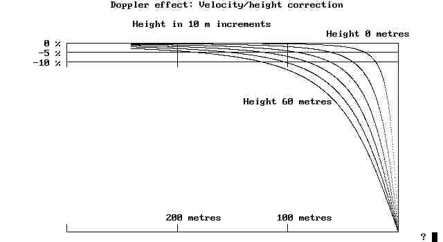
the model was about 50m up, so I was reasonably safe. Refer
now to the "Doppler effect: Velocity/height correction" diagram.
You must imagine the tape recorder is to the right of the
diagram, at 0 metres distance.
The top line on the graph marked "Height 0 metres" corresponds
to the model and tape recorder both at the same height, so
no correction is required. The curved lines relate to heights
of 10,20,30,40,50 and 60 metres.
As an example, note that when the model is 100m away, at height
50m, the curved line cuts the -10% error line: ie 10% too
slow. In the above analysis, this means the airspeed corrected
for height is 160 * 1.10 = 176 MPH.
There is no height correction chart for RPM
in the air. Provided Fcoming and Fgoing are determined at
equal distances from the tape recorder, the value f determined
above is true for any height.
This completes the analysis. The method looks really good,
as there is a big Doppler shift for fast models. In the case
of control-line models, it may be easier to get the in-air
RPM by putting the tape recorder in the centre of the circle,
but this does not give the airspeed. To get airspeed, put
the recorder just outside the circle at the same height as
the model.
If you do not want to go to all the trouble of setting up
this system, give me a call on (08) 9247 2481 and play your
tape to me over the telephone. I'll get back to you with the
results. If I'm not home, just play it to my answering machine.
Well is that cool or is that Supercool! Catch you all again
in '99.
|