Well folks, if you have never wondered why there is an air intake scoop on the belly of the P51 Mustang, read no further. You don't have the right stuff. I mean, why would any self-respecting designer put a scoop right where it would be scraped off in a wheels-up landing? The answer to this question was given in some detail by Leland Atwood in "Aeroplane" magazine, May 1999.
In that article, Atwood describes the "Meredith effect", which is a method for reducing the engine-cooling drag for the P51 Mustang fighter. If for no other reason, this is intriguing, as the Mustang was at least 20 MPH faster than the Spitfire using the same engine. Sacrilege. Having read this article of Atwood's many times, I was disappointed to find I still did not understand how the Meredith effect actually worked. Searching the internet, I found many other likewise confused folk: indeed: I even found one authoritative source that had part of the ducting system on backwards.
If only I could read Meredith's 1935 article itself. Nothing like going back to the original source, it cuts out the Chinese whispers from all the self-appointed experts. Incredibly, I was able to find the original article on the net, and print it out! You can too. The address is http://naca.central.cranfield.ac.uk/reports/arc/rm/1683.pdf
Where you get Atwood's article I'm not sure, but drop me a line and I'll see what I can do.
Either way, you need to have them both, as else you will have to live with my parrot-phrased version. But first a warning: one of these articles was written by an engineer, the other by a physicist. There is a difference in style and culture. Engineers are warm, gregarious folks who love to work as a team. Physicists can't remember their own name, let alone yours: they love being isolated in ivory towers where there are no telephones. Engineers do their sums using formulae produced by Aristotle, arguing with quotes from Socrates; Physicists just say "Newton". End of story.
Time now to move on to the subject of cooling drag. The new problem faced by designers in the 1930's era was the incredible growth in power of aircraft engines, from something like 600 BHP to over 2000 BHP in the Schneider trophy racing seaplanes. Accompanying this power growth, was the need to remove waste heat: the power in the wasted heat was of the order of 25% of the power generated by the engine. Getting rid of this heat was not just wasteful, but slowed down the aeroplane due to drag in the radiator or, for air-cooled engines, in the cooling fins.
This was serious, but even more so, the drag of the cooling system was to some degree proportional to the aircraft airspeed, while the power to move the radiator/cooling fins through the air went with roughly with the square of the airspeed, if not the cube! Thus designers began to realise there may be a limit to the speed piston-engine aircraft could achieve, not due to lack of power or airframe drag , but to the drastic cooling requirements of the engine.
Meredith's study of this cooling problem had two components. The first was that drag could
be reduced if the cooling air could be slowed before it reached the radiator/fins. The second was that the waste heat energy could be recovered and used to counter the drag. Fine words but at that era this was a new idea. The fact that Meredith had a valid solution is the reason his name is remembered, forever allied with the outstanding performance of the North American P51 Mustang.
In a nutshell, there are two physical behaviours of air that apply. The first is that air can be slowed down and its pressure thereby increased by making it flow through a divergent duct. The second is that air which is either hot or under pressure can have the internal energy of the air converted to kinetic energy: ie it can be speeded up, thereby changing momentum. Another name for "changing momentum" is thrust. This latter trick is performed when the air passes into a convergent duct.
This is such a good trick that we have names for these special ducts. The divergent duct is called a "diffuser", while the convergent duct is a "nozzle".
Meredith's really neat idea was to join these two ducts together, back to front as it were, with radiator/fins sandwiched between them. Now being such a spaced out guy (I know this from the way he wrote RM1683), he saw no need to include a diagram of this system in his report. Not a really helpful way to communicate his ideas, but not too baffling for Atwood, Kindelberger, Schmued and colleagues at North American Aviation to figure out. I would refer you to Atwood's article in Aeroplane, but the diagram so neatly drawn by Giuseppe Picarella is so misleading that one could say it was wrong, so I address these errors in the following paragraphs.
The flow into the diffuser (labelled divergent duct) is annotated with the words "Air enters and slows". True, but Meredith's analysis proceeds on the basis that the slowed air has increased pressure. The better annotation would have been "Air enters and slows, which causes an increase in pressure at the radiator position".
The label in the convergent duct (nozzle) reads "Air heated by radiator expands". Regrettably, the word "expands" in thermodynamics does not mean "increases in volume". The process taking place in the nozzle is "expansion": this latter word means that the energy in the form of heat is converted into kinetic energy; not at all the same thing as "expands". Atwood himself confounds the issue further in the text where he wrote "A 200F temperature rise expands the air some 40 percent, so it can be seen that the discharged air …has a larger volume and for a given pressure requires a larger discharge opening , providing some forward thrust. This is the same principle as that of the ramjet engine." Photos of the P51 in flight show the rear duct fully closed, leaving only a small exit area. Atwood's statement is not the process described by Meredith.
Finally, referring to the variable outlet, the label reads "Variable outlet restricts flow, creating back-pressure and therefore thrust". We have just seen that the function of the nozzle is to enhance flow, not to "restrict flow".
So if on studying this diagram you found it unhelpful, that is because it is unhelpful. I will now run through the manner in which Meredith showed how the duct worked, beginning with my diagram below.
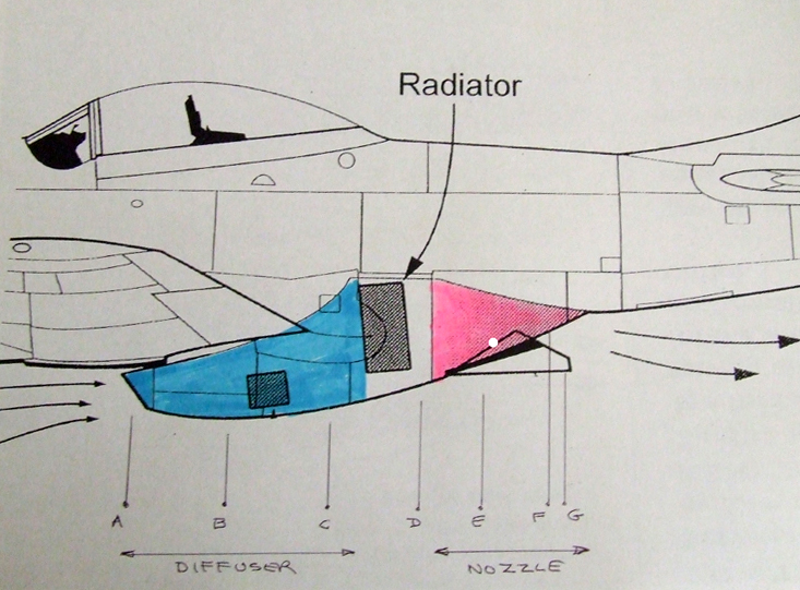
The code on the diagram indicates the condition of the air passing through the duct.
Position A: High speed air with ram pressure enters the diffuser
Position B: Air is slowing, pressure rising as the diffuser cross-section area increases.
Position C: Air is at minimum speed and highest pressure on entering the radiator.
Position D: Air has been heated on passage through the radiator. Pressure falls a little due to viscous losses in the radiator.
Position E: Thermodynamic expansion is taking place in the nozzle. Temperature of the air is falling as the heat energy content is converted to kinetic energy. Pressure is falling as the air speeds up down toward the exit.
Position F: Adjustable exit scoop is set for high speed flight. Temperature of the air is much reduced, but not all of the heat can be turned into kinetic energy. Pressure is close to ambient, while the exit velocity is close to matching the airspeed of the airplane. The momentum change going from radiator rear face to the exit is seen as thrust, cancelling the drag of the radiator.
Position G: The scoop is wide open for low speed operation, where the cooling needs must be met by low velocity of the air at position A. No thrust generated due to low pressure rise in the diffuser.
We begin with the diffuser. Air enters via a nicely shaped inlet: the inlet is nicely shaped because it is rounded, such a contour allowing fast moving air to enter the diffuser smoothly (no turbulence). Once past the inlet, the air finds itself in a large, smoothly contoured chamber. By a law of the behaviour of a gas, beautifully analysed by Bernoulli, the air slows down as it fills the chamber, while its pressure increases. The pressure increases because the kinetic energy of the incoming air is converted to potential energy in the form of air compression.
At the face of the radiator/fins, the air pressure is at a maximum. The greater the degree of compression, the better the air cools the radiator/fins, and the better the rear nozzle can do its job. A glance at the system in the P51 shows that the inlet area is much less then the area of the face of the radiator/fins. The greater the area at the radiator/fins, and the smaller the area at the inlet, the more pressure is gained.
Next we look at the radiator. The compressed and slowed air passes through the radiator, cooling the working fluid (water + ethylene glycol). The working fluid is passed to the hot and sweaty engine which in gratitude keeps on turning the propeller. The passage through the radiator is not without difficulty. The air passing into the radiator does not want to go: it has to squeeze past the tubes and fins in the hot radiator. The air has to be pushed through by the pressure acting on the face of the radiator. By the time the air gets through to the nozzle, some of the hard-earned pressure in the diffuser has been lost. With luck, or even good design at a pinch, only a small amount of pressure is lost, so that the pressure on the rear face of the radiator is not too different to that on the front face.
Entering the nozzle, we need that pressure and the heat surrendered by the radiator to the air.
The process of expansion (technical term) must now take place in the nozzle. That is, the energy of compression and heat is now converted to kinetic energy by passage down the nozzle. That is what nozzles do. Forget what Aristotle reckons, this is Newton hard at work: or, with his intellect, at play.
Now, this increase in kinetic energy is also a change in momentum of the air (Newton's second law), which is thrust. Now here is the trick. This duct system does not willingly accompany the airplane. It has to be dragged along, firstly because it is part of the airplane, and secondly because effort was expended working against the viscosity of the air. This viscosity retards flow over the duct surfaces, in compressing the air, in forcing it through the radiator, even getting it out of the nozzle, when all the processes are done. But Meredith showed that the thrust extracted from the heated air could exceed the drag of the whole cooling system provided the airplane was flying at over 300 MPH.
Recall at the start of this epistle, that designers in the 1930's thought that cooling drag could not be eliminated, that the speed of an airplane was limited by the cooling drag. Yet here is Meredith saying that an airplane flying at over 300 MPH could have no nett cooling drag. Not only that, but if waste heat from the exhaust could be added into the nozzle, then thrust could be gained which exceeded the cooling drag!
This is a revelation : this is a Eureka moment. This is genius! Reading Meredith's paper, after first muddling through his descriptions, one realises that the physics and the thermodynamics are at an elementary level. The maths is trivial. What a joy it was to unravel this seminal work of genius.
Converting this theory into metal was quite another matter. The guys at North American really had their work cut out to get the duct working. That they did so, under the extreme pressures of timelines and war production, speaks highly of their dedication and competence.
There is one aspect of this implementation work that amuses me, though it may be speculation. The air entering the inlet had to flow smoothly through the diffuser, or the desired pressure rise would simply not occur. The P51 diffuser is short, much more so than diffuser theory would wish. So when the original inlet was mounted close by the fuselage lower surface, a boundary layer problem arose as turbulent air from the fuselage spilled into the inlet, thereby ruining the smooth flow in the diffuser.
My amusement arises because this problem was readily noticed by the pilot, as he was practically sitting on the diffuser and thus subjected to all the bangs and crashing noises coming his way!
By contrast, the British attempt at implementation (and this was their theory) was somewhat less successful in the wing mounted radiator of the Spitfire. The boundary layer problem was not solved, the lower part of the wing surface and its accompanying boundary layer reducing the power of the diffuser. Neither was the pilot in a position to hear the turbulence in the diffuser.
In the immortal words of our Australian bushranger national hero, Ned Kelly, as he stood upon the gallows, "such is life". |