| Hi Supercool.
How about the following to add to your
Ducted Cooling Piece?
You are one of the few people who have taken a close look
at cooling a high performance model airplane engine. As you
correctly stated, significant gains are achievable through
a carefully designed cooling system. Starting out with the
basic premise that heat is energy and if this energy can be
recovered in some fashion, it's equivalent to increasing the
power of the engine which finally equates to a faster model.
|
 |
Miss
Trinidad
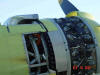
This is R-2000 powered Yak 3 with a Pete Law designed
ADI system. Note the attempt at creating exhaust
pumping effect through the cowl. Two outlets with
seven jet stacks on each side. |
North American Aviation spent countless hours
in the Cal. Tech wind tunnel tweaking the shape of the P-51
'Dog House' in order to maximize the Meredith effect. There
must be dozens of books written on the P-51 but the one I'd
recommend is the one written by Robert Gruenhagen; Mustang.
The Story of the P51 (Genesis Press). Most airplane books
tend to be what I call 'units and markings books', i.e.,.
not much in the way of technical detail, engineering aspects
or development but lots of details on what �' stencil markings
went where. In Gruenhagens' book, numerous photos are shown
depicting the various shapes and designs NAA engineers developed
for the dog house.
|
 |
Bristol
Hercules engine cut-away drawing |
The point of the forgoing is to stress the
fact that just because a huge amount of heat energy is dissipated
to the atmosphere it does not necessarily imply that it's
easy to capture. A good example of this is the Hawker Hurricane.
Similar placement of the cooling system as the P-51 but absolutely
no Meredith effect. With an air cooled radial, things get
a little trickier due to the confines of the cowl. However,
a carefully designed cowl can, at the minimum, reduce cooling
drag. To pull this off, as you correctly stated, take a look
at a top unlimited Reno Racer such as Furias, a modified Sea
fury powered by a Pratt & Whitney R-4360-63A or Rare Bear
a modified F8F Bearcat powered by a 'bitsa' Wright R-3350.
|
 |
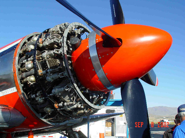
Bristol
Hercules cylinder |
In the case of Furias, an annular gap of 2'
is used and this has to take care of the cooling requirements
of a huge twenty-eight cylinder, four row radial. So how's
this pulled off? Fortunately, these ultimate hot rods have
the expertise of the world's best aerodynamicists at their
disposal. The late Bruce Boland, designer of the late lamented
Tsunami, was one of these experts who gave freely of his time
and expertise to assist the racers. Pete Law, another Lockheed
Martin thermo dynamics expert also assists with these projects.
|
 |
Critical
Mass
Note the after body. Highly modified Sea Fury powered
by a 3350 made up form the best components. |
Getting back to Furias, the trick, as
you mentioned in your article, is to slow down the incoming
air. This is achieved via a classic convergent/divergent duct.
In other words, a larger diameter spinner directs the air
through the aforementioned 2' annular gap and from there,
an aft fairing that covers the nose case and magnetos terminates
a the base of the first row of cylinders. The aft faring also
tapers down as it extends to the cylinders. The inside of
the cowl receives similar treatment, everything being flowed
for ideal expansion and pressure increase. Even these measures
are not sufficient to cool an R-4360 so seven spray nozzles
are built into the leading edge of the cowl nose bowl. At
race powers, water is injected into each of the seven cooling
plenums that make up the 4360 cooling system.
|
 |
Hi-Tech
Fosters
This is race #38 Precious Metal powered by a Griffon
58 with a 74 blower and Bendix PR-100 carb. |
In other words, raw water is squirted on to
the hot (500 degree head temps) cylinders. Additionally, copious
amounts of ADI (anti detonation injection) fluid is injected
directly into the engine. ADI fluid is made up of a 50/50
mix of water and methanol. Again, my good friend Pete Law
is responsible for 90% of the ADI systems used by the Unlimited
class racers.
|
 |
Sea
Fury oil cooler
Note the nice entry to the cooler core. It's a new
cooler that uses fin and tube technology rather
than the stock matrix cooler. Also note the Pete
Law designed spray bar. |
Yet another source of heat rejection, obviously
not applicable to a two-stroke is oil cooling. Pete has designed
a number of 'boiler' systems whereby the oil cooler, typically
a bundle of copper tubes which allows air to flow through
the tubes and oil to flow around the exterior of the tubes.
By immersing the oil cooler in a bath of water and allowing
the hot oil to boil off the water, cooling drag from the oil
cooler is eliminated.
|
 |
Rare
Bear afterbody
Note the fairing over the nose case that extends
to the base of the front row of cylinders. This
shape creates a nice convergent/divergent flow path
for the cooling air. |
|
 |
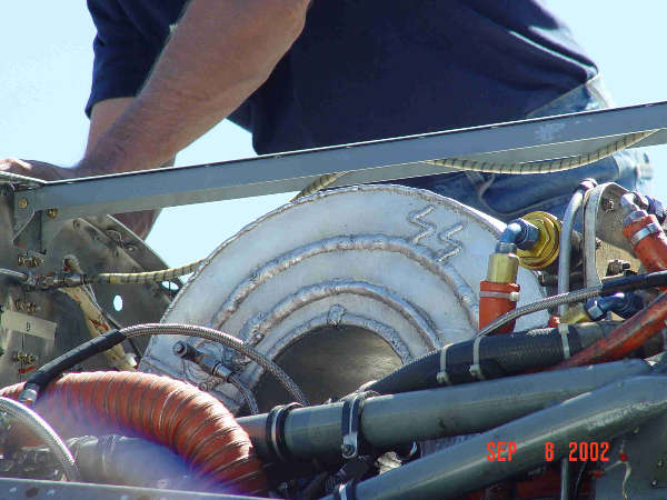
Rare
Bear ram scoop
Notes the two weld beads that support the flow splitters
to direct ram air into the Bendix PR-58 carburetor. |
Another Pete Law innovation is the use of spray
bars. In other words, the oil cooler, which is located in
a duct and exposed to the air stream, has water sprayed on
it from a spray bar system. Typically, the spray bars are
made from aircraft fire extinguisher tubing. Spray bars are
also used on coolant radiators for P-51s. It's a little known
fact that between ADI fluid, spray bar fluid and fuel, Dago
Red, the worlds' fastest P-51, will consume over 1,000 pounds
of fluid in a 15 minute race. That's right, � ton of fluid
in 15minutes. Of course, a 4360 powered racer such as Furias
will consume considerably more. Lets take a look at engine
design.
|
|
The
attached graph is one Pete Law generated for a presentation
to racers . They were astounded at the temperature
rises shown on this chart. And this temp. rise is
not just for induction air, it's applicable to all
air taken on board. That's why it is key to take
on the minimum amount air for cooling requirements
� or any other requirements. A good example is a
radial engine installation. Many folks, including
yours truly at one time, thought that the drag caused
by opening cowl flap on a radial installation was
due to the parasitic drag of the flaps sticking
out in the breeze. As it turns out, not so. The
vast majority of the drag is induced drag due to
delta MV component, the parasitic drag is inconsequential.
Pete spent 2 hours on the phone with me yesterday
explaining how all this works. It was tough sledding
(for me) because Pete has an IQ in the stratosphere
so when having a conversation with him you'd better
be prepared for some heavy duty laws of physics.
The foregoing also helps explain why spray bars
are so effective, they minimize the mass air flow
requirements for cooling thus contributing to a
remarkable reduction in drag. This may be effective
on models � but maybe not. Dunno; but it's worth
a shot. |
Air cooled radials were hampered by inadequate
cooling in the early years until luminaries such as Sam Heron
figured out the best way to manufacture an air cooled cylinder.
His method was surprisingly similar to that employed by Cox.
Screw the entire cylinder head onto the cylinder. The only
difference being the fact Cox reversed the gender of the treads,
i.e., they used a male thread on the head and a female thread
on the cylinder � other than that they were identical in concept.
I have often wondered if Cox got the idea when they first
designed the Thimble Drome in the late '40s from full size
practice.
|
 |
Attached
is remarkable piece of work that Pete Law did. Obviously
not applicable to models but nevertheless neat stuff.
Pete was instrumental in Darryl Greenamayer's record
breaking attempts with the Lockheed F-104 that got
the world's air speed and altitude records. So I've
attached a graph that shows ram temp rise for that
aircraft. The F-104 info. Is a the lower left, the
rest of the chart shows SR-71 performance figures
� Pete was the chief thermo guy on that project.
This stuff is all now de-classified but Pete told
me that Air Force pilots cruised at a 'conservative'
Mach 3 on missions..!!! Pete also developed a water
injection system for both the F-104 and the SR-71
in order to reduce ram temp. rises. It was never
fitted to the SR-71, they figured the Russians couldn't
catch it even without water. But one could just
imagine the instant vaporization of the water as
it hit 800 degree air. |
After Heron established the basic concept of
how to design an air cooled cylinder, the next hurdle was
to increase the number and depth of cooling fins. By the early
1940s it was apparent that the limitations of casting technology
had been reached, but horsepower was now restricted because
heat could not be rejected fast enough. The answer was actually
developed in the late '20s, early '30s by Roy Fedden who was
responsible for all the mighty Bristol radials. The solution
was to forge the cylinder head out of a solid aluminum billet
and then cooling fins could be machined in as closely and
deep as necessary. By the end of the big high horsepower radial
era, cylinders on engines such as the R-4360 were absolute
jewels. Finning was so close and deep, they actually looked
fragile, which in fact they were.
|
 |
Michael
Brown's ram scoop
Michael Brown picked up an additional 10in.Hg. manifold
pressure or about 400 � 500 horsepower with this
new (for 2002) ram scoop on his 3350 powered Sea
Fury. Note the bead of weld as the scoop transitions
through 90 degrees. This is the flow splitter inside
the scoop. He finished 2nd. In the final Gold Race. |
However, it was the only way to get the maximum
surface area exposed to the cooling air stream which is a
nice segway into the next aspect of cooling air cooled engines.
When cooling air enters a cowl, it's important to ensure that
every ounce of that air is put to good use by cooling something.
No use in just having a cylinder stuck in the breeze and hope
that some air will do its job. To this end, Pratt & Whitney,
Bristol and all the other manufacturers of large air cooled
radials spent hundreds of design hours perfecting baffles
that would capture cooling air as it entered the cowl and
ensured that it was forced around the cylinder and through
the fins. Bristol, in particular, had a significant challenge
ensuring that its sleeve valve engines received sufficient
cooling air down into the depths of the junk head. Once the
air had passed through the cylinder it had to be dumped over
board. But even here, careful design of the outlet directed
cooling air through a fairing colloquially known as a dish
pan. Mass air flow through the cowl was controlled via a ring
of flaps called cowl flaps. The greater the mass air flow
through the cowl, the greater the drag. So it was incumbent
upon the flight engineer to ensure that the ideal cylinder
head temperature was maintained; too high and the engine would
be cooked, too low and excessive drag was created.
|
 |
Furias
Furias powered by an R-4360-63A with a -59 nose
case. Runs 68in. Hg. at 3,100rpm. Quite conservative
for a racer. Laps around 420. |
|
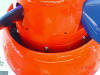 |
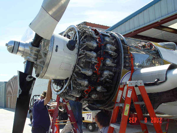
Furias
Spray nozzles
This shows the 2' annular gap and how the spray
nozzles are arranged around the nose bowl. Hard
to imagine that such a narrow gap can feed enough
cooling air to a massive 28 cylinder 4,360 cubic
aircraft engine. |
Exhaust is another good source of energy. There
are several ways to utilize exhaust energy, most of which
would be inapplicable to a model but worth looking at just
the same: (i) turbosupercharging, (ii) jet stacks, in othe
words utilize the thrust which is typically 400 pounds for
a Merlin, (iii) augmenter system and (iv) turbo compounding
whereby the exhaust energy is used to drive a gas turbine
which feeds power back to the engine.
|
 |
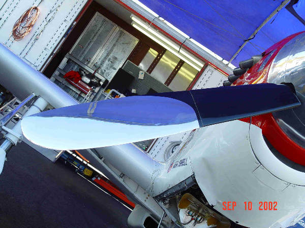
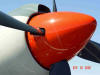
Strega's
propeller blade |
Much of the foregoing has absolutely no application
or use in model applications with one or two exceptions. First
off, the interior shape of the cowl is just as important,
if not more so, than the exterior. So it would be a good idea
to design a convergent/divergent shape into the front half
of the cowl. Next, cooling air that enters the cowl should
all be put to good use doing what it's supposed to do; carry
away heat rejected through the cooling fins. And once the
air has picked up the rejected heat, the exit duct should,
again, be given a lot of thought. This includes the shape
and the exit area. It may be possible to design an augmenter
system whereby the exhaust pulses are used to 'pump' cooling
air through the cowl. Convair designed a twin engined commuter
aircraft powered by a pair of Pratt & Whitney R-2800s
in the late 1940s. The eighteen exhaust stacks were utilized
to pump cooling air through the cowl. Exhaust and cooling
air were mixed and dumped overboard over the trailing edge
of the wing. It was claimed that 500 pounds of thrust and
20mph resulted from this innovation. Cast cooling fins are
not the optimal design. Machining them in from solid billets
offers a lot more flexibility to the extent more and deeper
cooling fins can be used and thus reduce cooling drag. Remember,
the less air that enters the cowl, the less drag results.
|
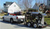 |
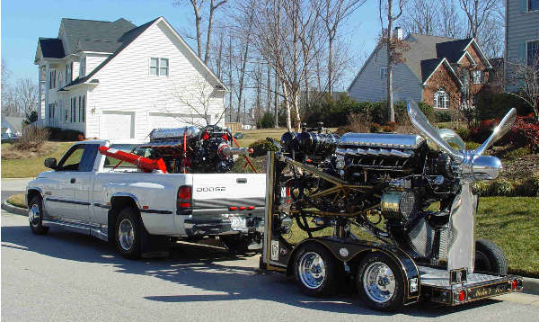
Rolls
Royce power
The attached pic. shows my R-R Griffon (in the bed
of my truck) and the Merlin. As I mentioned, I'm
in the process of returning to Florida so I've temporarily
parked those two engines in a local museum. |
Another aspect that hasn't been touched upon
is that of induction ram recovery. With a front induction
engine, a carefully designed ram duct for the induction system
could gain 1 to 2 in.Hg. at 150mph. This is a significant
amount. Again, look at a high performance WWII fighter for
good ram air induction systems. The opening, which should
be normal to the air flow, must be sized correctly; too large
and air spills out of the ram air duct and creates drag. Too
little and full ram recovery is not possible. If, for arguments
sake, the induction venturi is at 45 degrees, a duct that
'bends' the air from horizontal to 45 degrees is required.
And it may even need a flow splitter within the duct to further
assist the ram effect. For a rear induction engine a similar
duct can be used and again, the duct should discharge into
the venturi, preferably well sealed. Only with this system
the air needs to bend through 180 degrees.
|
 |
1.5"
annular gap on Sea Fury
This is Nelson Ezell's Sea Fury powered by a Wright
R-3350-26W. The annular gap is 1-1/2 inches and
it cools just fine. Unfortunately, I couldn't get
a picture of the after body but many of the 3350
powered Sea Furys' use a 1-1/2' or 2' gap. Of course,
a lot of heat is rejected through the oil coolers
which have spray bar assist. |
For now, we won't go into reduction gearing
but it does not have to be difficult or bulky. The Farmen
epycyclic system offers the most compact system that would
easily fit within the confines of a speed pan.
|
 |
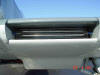
P51
Mustang cooling duct |
Authors' background. Recently joined NASS.
In the late 50s and early 60s I did all classes of tam racing.
Currently I collect full size engines and restore them to
running condition. Presently have (2) P& W R-4360s. R-R
Merlin, R-R Griffon, P&W R-2800 and Continental IV-1430.
Authored two books on aircraft engines: 'Allied Aircraft Piston
Engines of World War II' and R-2800, Pratt & Whitney's
Dependable Masterpiece'. Both books are available through
the publisher www.SAE.org
Author of numerous magazine articles on automotive and aviation
subjects.
I'm also the executive editor of 'Torque Meter' the journal
for the Aircraft Engine Historical Society.
www.enginehistory.org
Very truly yours, Graham White.
|