Loyal readers who have been following the HoG (Heart
of Gold) saga may recall that I have been trying at attain
good line tension at 50 MPH. Line rake, offset thrust-line
and radical engine offset have all failed to provide the line
tension I need for solid overheads.
The only variable remaining is fuselage lift. Having no fuselage,
the HoG would be at a disadvantage if fuselage lift were a
necessity for good line tension. The flight of
many models, such as in F3D and F2A, includes knife-edge flight:
in these instances, the lift supporting the weight of the
model must come from the fuselage, plus a small component
due to engine inclination.
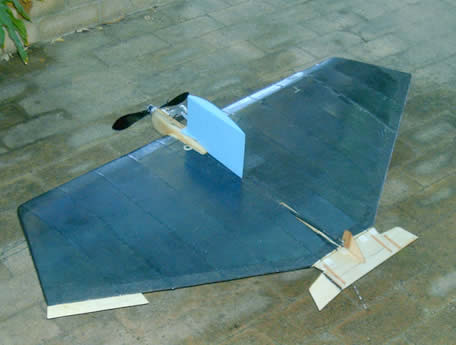
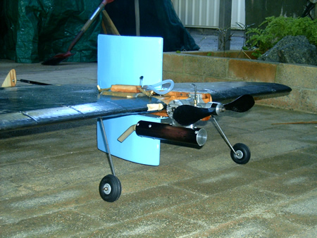
To test this hypothesis, I fitted the HoG with centre-mounted
stub X-wings. Incidence was made variable by mounting the
stub wings on a steel shaft. Hopefully, this adjustment would
enable me to adjust line tension to values providing solid
tension in overheads. These mods are clearly shown in the
photos.
Test flying provided the following facts:
1. Line tension in overheads was not noticeably increased.
2. Drag from the stub wings was high, making it impossible
to glide the final lap, as required in the F2B pattern.
3. Increasing incidence only increased the drag.
I am forced to conclude that line rake, thrust-line offset,
engine offset and X-wings fail to provide solid, reliable
tension in overhead manoeuvres on stunters.
The certain methods are to reduce model weight and fly fast
(like 5 second laps).
Methods involving rolling motions, such as tip, weight, differential
wingspan and differential flaps can increase tension, but
at the expense of wobbly square turns. Motor set-ups (2-4
break) that increase speed during manoeuvres are also effective,
at the expense of fast reflexes in the pilot (read “youthful
pilot”)
All very sad. Anybody out there got a solution?
In response: from Alwyn Smith
I have read all the different articles that you have written
in the A.C.L.N. over a number of years.
My introduction to C/L flying was on the Esplanade in Perth
in about 1948, and I still fly C/L.
I was very interested in your latest article about LINE
TENSION, as I have been trying to tell C/L fliers, my ideas
for about 50 years now.
I have amongst my collection of C/L models in Melbourne,
an Aeroflyte Aurora fitted with an OS Max 40 FSR. I acquired
this model ready built about 20 years ago. The Aurora is very
nose heavy with the 40 FSR, ( I seem to remember it weighs
about 11.5 Oz or 330 Gms ) and the model was designed to take
an engine like an OS Max S 35 at about 8.0 Oz or 230 Gms.
The model was so nose heavy it would not do aerobatics,
and had such a massive line tension, I was not game to fly
it level as I felt it might break the lines.
I added a square of lead, under the Tail Plane, and then
after a test flight, added another piece of lead, until I
had about nine 1” x 1” pieces of lead glued under
the T/P
The C/G was moved back until the model would perform aerobatics
correctly. At the same time the LINE TENSION decreased, and
it became a very nice flying model.
On one of my trips to England I was at Old Warden, and talking
to John Stroud, who was at the time, editor of Aeromodeller.
He had been given one of the new PAW 60 Diesels, and built
a twice size Aeromodeller A.P.S. Unlimited for it. The photo
of this model appeared on the front cover of Aeromodeller.
I helped John prepare the model for flight. In the article
in Aeromodeller John had said how the model would not do aerobatics
as the model was TOO nose heavy due to the weight of the PAW
60 ( I think about 16 Oz or 560 Gms ), and would pull your
arm off.
When I was holding the model for John to start the engine,
I asked if it was still nose heavy, and John said “
No” He had added lead to the underneath of the trailing
edge, and turned the model over to show me. I commented that
the model would also have lost the MASSIVE line tension. John
just looked at me and called me a HERETIC.
Ian Smith from Sydney was in Melbourne and contacted me
as he asked if he could visit my home to see my collection
of models and engines.
We got into a discussion about Line Tension, Control Plate
and Pivot point, and Lead out positions. I told Ian I have
always thought that ALL the experts were WRONG, and the main
point I made was that I believe the model is supported at
the PIVOT POINT, not on the wing tip guides. Ian like John
Stroud told me I did not know what I was talking about, and
all the experts have agreed that the position of the pivot
point in the bell crank is unimportant. He mentioned the diagram
that has appeared in many magazines, showing a cardboard cut
out of a model, and how it will always hang with the C/G in
the middle of the supporting line.
I had the same discussion with Russell Wright many years
ago, and Russell told me that you must have Offset Rudder
and Offset Engine to get line tension. I pointed out to Russell
that I had a number of combat models that had NO rudder and
No engine Offset, and they ALL had GOOD Line tension, and
held out in overhead maneuvers
I claim that the Line Tension comes from the TURNING COUPLE
between the C/G and the Pivot Point, and the final line tension
comes from the speed and weight of the model. Look at a speed
model and have a look at the distance between the pivot point
and the C/G. They are very close together. If the C/G was
TOO far ahead of the Pivot Point, the nose of the model would
YAW out and create DRAG
I have been told that my theory cannot be correct as Paul
Turner from Sydney built a model with the Control Plate well
back near the trailing edge of the wing, and it made NO difference
to the Line Tension. I have not seen this model, or spoken
to Paul about his model
I have always built my C/L models with the Pivot Point slightly
backward of the position shown on the plan, and my front wire
runs parallel to the leading edge of the wing, if the model
has a straight leading edge. I have never found it necessary
to have my leadouts swept back. I do agree that the trim can
be adjusted by having the leadout guides adjustable, but that
is due to the nose of the model being pointed OUT, just like
modelers claim you need engine offset to obtain line tension,
but you tried this and found it not really effective.
I still claim that the LINE TENSION comes from the TURNING
COUPLE between the C/G and the Pivot Point, and the SPEED
and WEIGHT of the model
You did ask at the end of your article in May 2007 A.C.L.N.
No 110 for any other ideas.
Alwyn Smith
Caloundra May 2007
|