The task for the next few parts of this series on propeller design is to produce a computer code for the design process. To achieve this, we need a clear diagram of how the aerodynamic forces play on each blade element. This could be easier said than done. The idea of considering the propeller blade as a series of pieces all joined together was published by William Froude in 1878. This idea was extended by Drzewiecki (pronounced jee-vee-yet-ski), who also suggested the idea of applying airfoil data to each element. This enabled him to sum these forces over all elements to produce the thrust and torque for a whole propeller. The main assumption in this process is that the blade elements act independently, which turns out to be good enough.
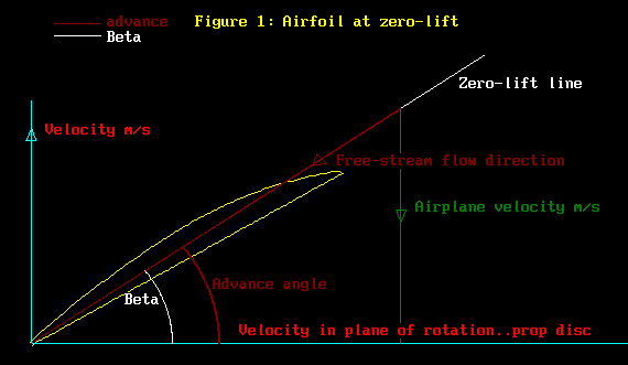
Examine Figure 1 below, which is our starting point. The figure introduces the important concept of an airfoil operating at zero lift. The airfoil section is set at an angle, which represents the blade twist. The air inflow, the free-stream flow in this instance, is the result of the airplane moving forward while the blade element itself is rotating around the propeller axis. The leading edge of this cambered section is slightly below the inflow, resulting in zero thrust for the blade element.

The angle of the airfoil section chord-line below the inflow is called the zero-lift angle (not surprisingly). The zero-lift angle measured against the chord-line is given with surprising accuracy by the expression
zero-lift angle = -ATN(camber/(1-camber high point)) [radians]
For a well known section such as Clark-Y, this angle is about -4 degrees, again a surprising angle. My apologies, but I forget where I found this expression; it is like gold to a computer programmer! For further information on zero-lift angle, see Footnote 1 below.
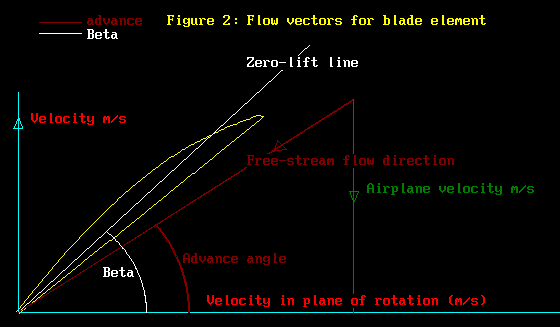
Now that was useless, wasn't it! Lets move on to something with more meat. Figure 2 has the airfoil section twisted above the free stream flow. That's nice, we should get some lift from the airfoil and some thrust from the blade element. Note carefully: I have persisted drawing the zero-lift line, ignoring completely the chord-line. But why? Well, the chord-line has no aerodynamic property; this diagram is about aerodynamic forces, so my analysis treats the chord-line as of no use, other than to provide a geometric property which we can actually measure with an instrument, say a protractor.

This is the diagram that Drzewiecki probably used. The angle formed between the free-stream and the zero-lift line is used to get the lift, from charts of lift versus angle-of-attack. Now that was a problem, as these charts nowadays are for wings of infinite aspect ratio! However, back then, charts were available for aspect ratios of 6 (wind tunnel models). So those were the charts that were used! As it turns out, the results so obtained were quite helpful, if not super accurate. For more on this, you might like to refer to Wilbur Nelson's 1944 book, "Airplane Propeller Principles". For more on the effect of aspect ratio on the lift-slope (lift versus angle-of-attack), see Abbot and Von Doenhoff, "Theory of Wing Sections", 1959.
Now this problem of aspect ratio was not going to go away. You see, the problem is that the free-stream airflow in Figure 2 IS NOT that which strikes the airfoil! Now one of us is mad, and I vote for you! The flow of air over the airfoil is complex, the surface speed varying everywhere: speeding up over the top, slowing down over the bottom, a real dogs breakfast. Some very smart professor types decided to replace all that flow with a single quantity, the DOWNWASH. This down wash and the free-stream interact mutually, the interaction being called "interference". The result is a new flow, the INDUCED flow, being the result of the interaction.
Figure 3 has 2 new lines on it. These are the DOWNWASH and the INDUCED flow. This is a whole new ball-game, believe me. Firstly, the induced flow is a real flow. The induced flow has some remarkable properties. The velocity of the induced flow is slightly LESS then the velocity of the free stream! Well, if you recall that the mean speed over the top of an airfoil is greater than the free-stream speed, while being slower than the free-stream on the undersurface, then perhaps this is just some more aerodynamic magic. But true, none the less. It gets worse.
Secondly, the induced flow is that which belongs to infinite aspect ratio wings! Notice that the down-wash vector is perpendicular to the induced flow vector. That is the tip-off: this is the situation for infinite aspect ratio wings! Now for the pay-off. Those silly charts of lift versus angle-of-attack for infinite aspect ratio wings can now be used to find the true lift of the blade element! We really need that angle-of-attack formed between the induced line and the zero-lift line. Hope you can see now why we need these diagrams!
Well, not really. It turns out that most thin airfoils have the same lift-slope for infinite aspect ratio, mainly 0.1 per degree angle of attack (measured from zero-lift at zero angle-of-attack) . More gold for the computer programmer! (btw, for wing aspect ratio 6, the lift-slope is 0.0715 per degree). See Footnote 2 for more on lift-slope versus aspect ratio.
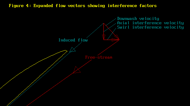
Here is another diagram, Figure 4. This time, I have thrown away everything except the interference effects. Repeated are the free-stream, the down-wash and the induced flow line, as in Figure 3. New are the components of the down-wash, the interference factors. The axial component provides the thrust force, while the swirl component is a nuisance, absorbing power without producing thrust. The swirl component results in the air wanting to rotate around the fuselage, not good, but inevitable. You got axial, you got swirl. The swirl absorbs torque, the absorbed torque producing thrust. So a propeller is a torque converter. As it happens, a very efficient device, as the drag losses associated with moving air around are low.
As a side-line, notice that I have had nothing to say about airfoil section drag. The drag is really quite low compared to the lift, to the point where quite adequate propellers can be designed ignoring the drag altogether! Even madder, there are pre-computer methods of prop design which consider only one blade element, that at the 3/4 radius! If you have ever had to do all your calculations using a slide rule, or an electric motor driven calculating machine which jammed up every so often, then you can have sympathy for these methods. Indeed, typing the text here on a word-processor makes you curse the day you were born into an era of the manual typewriter, with copies done on carbons.

We are nearly done. Figure 3 and Figure 4 provide all we need to analyse a propeller; oh, plus a computer to do the sums. The magnitude of the interference factors can be found by comparing the aerodynamic forces to the momentum change given by the downwash. For more on this, try Fred Weick's 1930 book "Aircraft Propeller Design".
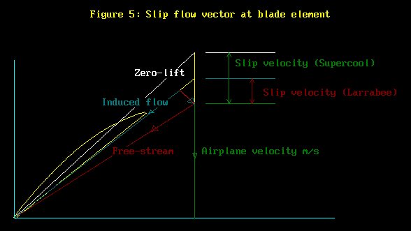
Just one more concept and we are finished with Part 4. Figure 5 gives us a definition of "slip".
Well, 2 actually, one is mine! As it happens, Larrabee's one is correct, but it's worth a bit of discussion.

The point here is that sometimes people call a propeller an airscrew. A regular woodscrew passes thru wood, just as though it produces no thrust. So my "slip" considers a propeller as a true "screw", moving along its zero-lift line thru the wood. Slip occurs because the air does not stay fixed like wood, being deflected away from the "screw". Larrabee, on the other hand, considers that the"screw"
moves along the induced flow line. He calls this "rigid air": fair enough, but the airfoil is producing lift at this angle; not the behaviour of a screw. See "Propeller Design and Analysis for Modellers", NFFS Symposium report,1979, by E.E Larrabee.
Seems silly labouring this point, but here is the rub. The most efficient propellers have constant slip along the whole blade. We need to know the slip to design the prop: in particular, to determine the radial distribution of chord. See also Footnote 3.
OK. Take a rest, this is the end of Part 4. You will be tested in Part 5, the actual code for designing a propeller. Cheers.
Footnote 1: The influence of section camber on lift is addressed on page 2-15 of S.F.Hoerners 1975 edition of "Fluid-Dynamic Lift". Figure 25 on page 2-15 summarises the zero-lift angle for various airfoil types, over a range of cambers and camber locations. This figure validates my use of the formula for zero-lift angle for evenly cambered sections, as might be adopted for use in propellers.
A further determination of zero-lift angle, similar to mine, is given by R.T Jones, page 53 of the 1988 publication "Modern Subsonic Aerodynamics". By referring to camber lines of circular or of parabolic form, he fixes the value of the camber high point location at 0.5. In fact, the zero-lift angle varies with the position of the camber high point location. Deleting "at the 50% chord point" fixes this problem. For me, anyway. My own airfoils have a camber line which is part circular, the remainder as for the NACA 4-digit sections.
Abbott and Von Doenhoff also give methods for finding zero-lift angle devised by Munk and Pankhurst. For the airfoils that interest me, these methods do not appear to offer more than the very simple formula above. This text also describes how the various NACA wing sections were designed. The influence and importance of the camber line then becomes very apparent. For the NACA 4 digit sections, the camber line was first chosen, then the thickness form of Clark-Y was wrapped around this camber line. The actual coodinates of the Clark-Y thickness form were
laid out on normals to the camber line. Messy but rigorous.
My own camber line is a pale shadow of the scientific care taken at NACA. I found, along with others, that the NACA sections are too blunt at the leading edge. Even more pragmatically, I could not machine the section profiles into my aluminium moulds. THe sections I use for model props are often as small in chord as 8mm. Since the smallest cutter I can use has 3mm diameter, it became clear that the radius of curvature of the cutter greatly exceeded the radius of curvature of the section, especially at the upper leading edge. This was fixed by adopting a circular camber line with radius of curvature greater than that of the cutter! Hence was born the Supercool 4-digit family of airfoils. You can imagine my delight when team race props using these sections were immediately successful at the European Championships: in fact, the props suddenly became world class performers.
This all made me wonder why designers, such as Selig, Donovan and Fraser, go to such efforts to make subtle changes in airfoil sections. It may be the application that matters. With propellers, the force coefficient for drag is really quite secondary and can almost be ignored.By contrast, glider sections need to have low drag at low angles-of-attack (for speed between thermals), while propeller sections are operated at their best L/D. Even so, I know glider pilots who would rather have Clark-Y in turbulent air conditions than any of the modern laminar flow sections. While I am rattling on, I was in Switzerland recently (2010) and was astonished to see sailplanes flying over the Yungen Frau! Followed soon after by tante Ju! Even crazier, from my backyard in Langnau I watched a sailplane trying to ride the storm fronts passing overhead!
Footnote 2: Godsey and Young in their 1949 publication "Gas Turbines for Aircraft" give a neat empirical formula for the lift-slope. To quote: The slope K of the Cl vs. alpha (in degrees) curves depends principally upon the aspect ratio AR and obeys the empirical relation
K = 0.1/(1+2/AR)
Foot note 3: Propeller efficiency has 2 components, called Profile efficiency and Induced efficiency. These 2 are incompatible. Design attempts to improve one inevitably degrade the other. Thus designing a propeller with maximum induced efficiency, by making the slip constant, does not necessarily produce the propeller of highest efficiency overall. A practical (read: rough and ready) approach is to choose a blade element angle-of-attack which gives the best L/D, and then adjusting the chord to make the slip constant. This would not be very interesting, were it not for the fact my definition of slip cannot produce constant slip along all the blade elements, whereas Larrabee's does.
The failure of my slip appears to be related to the pure geometry of the blade twist. So nothing lost there. But we will revisit this problem in Part 5 of this series, wherein we introduce a computer algorithm for generating the prop design with the most simple set of equations. |